- 您現(xiàn)在的位置:買賣IC網 > PDF目錄225526 > VKP100LT512-(6)/H (CD TECHNOLOGIES INC) 3-OUTPUT 100 W DC-DC REG PWR SUPPLY MODULE PDF資料下載
參數(shù)資料
| 型號: | VKP100LT512-(6)/H |
| 廠商: | CD TECHNOLOGIES INC |
| 元件分類: | 電源模塊 |
| 英文描述: | 3-OUTPUT 100 W DC-DC REG PWR SUPPLY MODULE |
| 文件頁數(shù): | 3/6頁 |
| 文件大小: | 205K |
| 代理商: | VKP100LT512-(6)/H |

VKP100xT
REV A
10/2000
Page 3
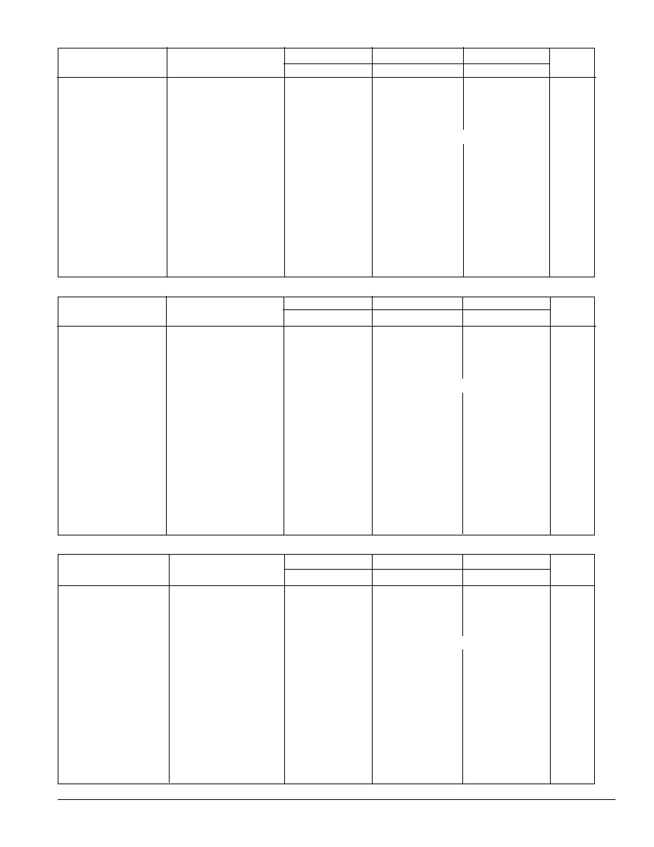
OUTPUT 1
OUTPUT 2
OUTPUT 3
PARAMETER
CONDITIONS
Min
Typ
Max
Min
Typ
Max
Min
Typ
Max
UNITS
Output Power
50
100
25
50
25
50
W
Set Point Voltage
T
CASE = 25°C, IO Max
3.3
15.85
V
Output Current, I
OUT
0.5
15
30.3
1.66
3.4
1.66
3.4
A
Output Ripple, p-p (see fig. 10)
DC to 20MHz
100
200
125
250
125
250
mV
Output Adjust Range
See Application Notes
3.15
4
Dependent on V1
V
Output Temperature Drift
.02
.05
.02
.05
.02
.05
%/°C
Line Regulation
V
IN, Min≤VIN≤VIN, Max
I
O = IO, Nom
.02
.05
0.6
0.8
0.6
0.8
%
Load Regulation
No Load to Rated Load
0.3
0.5
%
Current Limit Inception
Other Outputs No Load
38
5
A
Short-Circuit Current
30
33
4.2
5
4.2
5
A
Transient Response
50 to 100% Load Step
Peak Deviation
150
250
mV
Settling Time
V
OUT, 1% of VOUT, Nom
35
50
Sec
Overvoltage Limit
4.25
4.75
V
Efficiency
I
OUT1=15A, (IOUT2+IOUT3) = 3.4A
85
86
%
F.L. V
IN=Nominal
See Regulation Curves
VKP100xT315 OUTPUT SPECIFICATIONS Specifications are at T
CASE = +40°C nominal input voltage unless otherwise specified.
OUTPUT 1
OUTPUT 2
OUTPUT 3
PARAMETER
CONDITIONS
Min
Typ
Max
Min
Typ
Max
Min
Typ
Max
UNITS
Output Power
50
100
25
50
25
50
W
Set Point Voltage
T
CASE = 25°C, IO Max
5.1
12
V
Output Current, I
OUT
0.5
10
20
2.1
4.2
2.1
4.2
A
Output Ripple, p-p (see fig. 10)
DC to 20MHz
100
150
250
150
250
mV
Output Adjust Range
See Application Notes
4.7
5.5
Dependent on V1
V
Output Temperature Drift
.02
.05
.02
.05
.02
.05
%/°C
Line Regulation
V
IN, Min≤VIN≤VIN, Max
I
O = IO, Nom
.01
.05
0.6
0.8
0.6
0.8
%
Load Regulation
No Load to Rated Load
.2
.4
%
Current Limit Inception
Other Outputs No Load
26.6
5.8
A
Short-Circuit Current
16.6
20
5
5.8
5
5.8
A
Transient Response
50 to 100% Load Step
Peak Deviation
200
300
mV
Settling Time
V
OUT, 1% of VOUT, Nom
35
50
Sec
Overvoltage Limit
6
6.2
6.5
V
Efficiency
I
OUT1=10A, (IOUT2+IOUT3) = 4.2A
86
87
%
F.L. V
IN=Nominal
See Regulation Curves
VKP100xT512 OUTPUT SPECIFICATIONS Specifications are at T
CASE = +40°C
nominal input voltage unless otherwise specified.
OUTPUT 1
OUTPUT 2
OUTPUT 3
PARAMETER
CONDITIONS
Min
Typ
Max
Min
Typ
Max
Min
Typ
Max
UNITS
Output Power
50
100
25
50
25
50
W
Set Point Voltage
T
CASE = 25°C, IO Max
5.0
15.3
V
Output Current, I
OUT
0.5
10
20
1.66
3.4
1.66
3.4
A
Output Ripple, p-p (see fig. 10)
DC to 20MHz
100
150
125
250
125
250
mV
Output Adjust Range
See Application Notes
4.7
5.5
Dependent on V1
V
Output Temperature Drift
.02
.05
.02
.05
.02
.05
%/°C
Line Regulation
V
IN, Min≤VIN≤VIN, Max
I
O = IO, Nom
.01
.05
0.6
.8
0.6
.8
%
Load Regulation
No Load to Rated Load
0.2
0.4
%
Current Limit Inception
Other Outputs No Load
26.6
5
A
Short-Circuit Current
16.6
20
4.2
5
4.2
5
A
Transient Response
50 to 100% Load Step
Peak Deviation
200
300
mV
Settling Time
V
OUT, 1% of VOUT, Nom
35
50
Sec
Overvoltage Limit
6
6.2
6.5
V
Efficiency
I
86
87
%
F.L. V
IN=Nominal
VKP100xT515 OUTPUT SPECIFICATIONS Specifications are at T
CASE = +40°C nominal input voltage unless otherwise specified.
See Regulation Curves
相關PDF資料 |
PDF描述 |
|---|---|
| VKP100LT312-(8)/H | 3-OUTPUT 100 W DC-DC REG PWR SUPPLY MODULE |
| VKP60LS12A/H | 1-OUTPUT 60 W DC-DC REG PWR SUPPLY MODULE |
| VKP60LS03B/H | 1-OUTPUT 60 W DC-DC REG PWR SUPPLY MODULE |
| VKP60MT312-8/H | 3-OUTPUT 60 W DC-DC REG PWR SUPPLY MODULE |
| VKP60MT315-8/H | 3-OUTPUT 60 W DC-DC REG PWR SUPPLY MODULE |
相關代理商/技術參數(shù) |
參數(shù)描述 |
|---|---|
| VKP100LT515 | 功能描述:DC/DC轉換器 DISC BY MFG 2/02 100W 24V +/-5/15/15 RoHS:否 制造商:Murata 產品: 輸出功率: 輸入電壓范圍:3.6 V to 5.5 V 輸入電壓(標稱): 輸出端數(shù)量:1 輸出電壓(通道 1):3.3 V 輸出電流(通道 1):600 mA 輸出電壓(通道 2): 輸出電流(通道 2): 安裝風格:SMD/SMT 封裝 / 箱體尺寸: |
| VKP100MT312 | 功能描述:DC/DC轉換器 100W 48V+/-3.3/12/12 RoHS:否 制造商:Murata 產品: 輸出功率: 輸入電壓范圍:3.6 V to 5.5 V 輸入電壓(標稱): 輸出端數(shù)量:1 輸出電壓(通道 1):3.3 V 輸出電流(通道 1):600 mA 輸出電壓(通道 2): 輸出電流(通道 2): 安裝風格:SMD/SMT 封裝 / 箱體尺寸: |
| VKP100MT312-6 | 制造商:未知廠家 制造商全稱:未知廠家 功能描述:Analog IC |
| VKP100MT312-8 | 制造商:未知廠家 制造商全稱:未知廠家 功能描述:Analog IC |
| VKP100MT312C | 制造商:MURATA-PS 制造商全稱:Murata Power Solutions Inc. 功能描述:100 Watt, Dual/Triple Output, Half Brick DC/DC Converter |
發(fā)布緊急采購,3分鐘左右您將得到回復。