- 您現(xiàn)在的位置:買賣IC網(wǎng) > PDF目錄359408 > VO4A486L-Q116A VENTIL EXCEL N C OEFFNUNG 2.0MM PDF資料下載
參數(shù)資料
| 型號(hào): | VO4A486L-Q116A |
| 英文描述: | VENTIL EXCEL N C OEFFNUNG 2.0MM |
| 中文描述: | VENTIL的EXCEL數(shù)控OEFFNUNG 2.0MM |
| 文件頁數(shù): | 3/6頁 |
| 文件大?。?/td> | 128K |
| 代理商: | VO4A486L-Q116A |

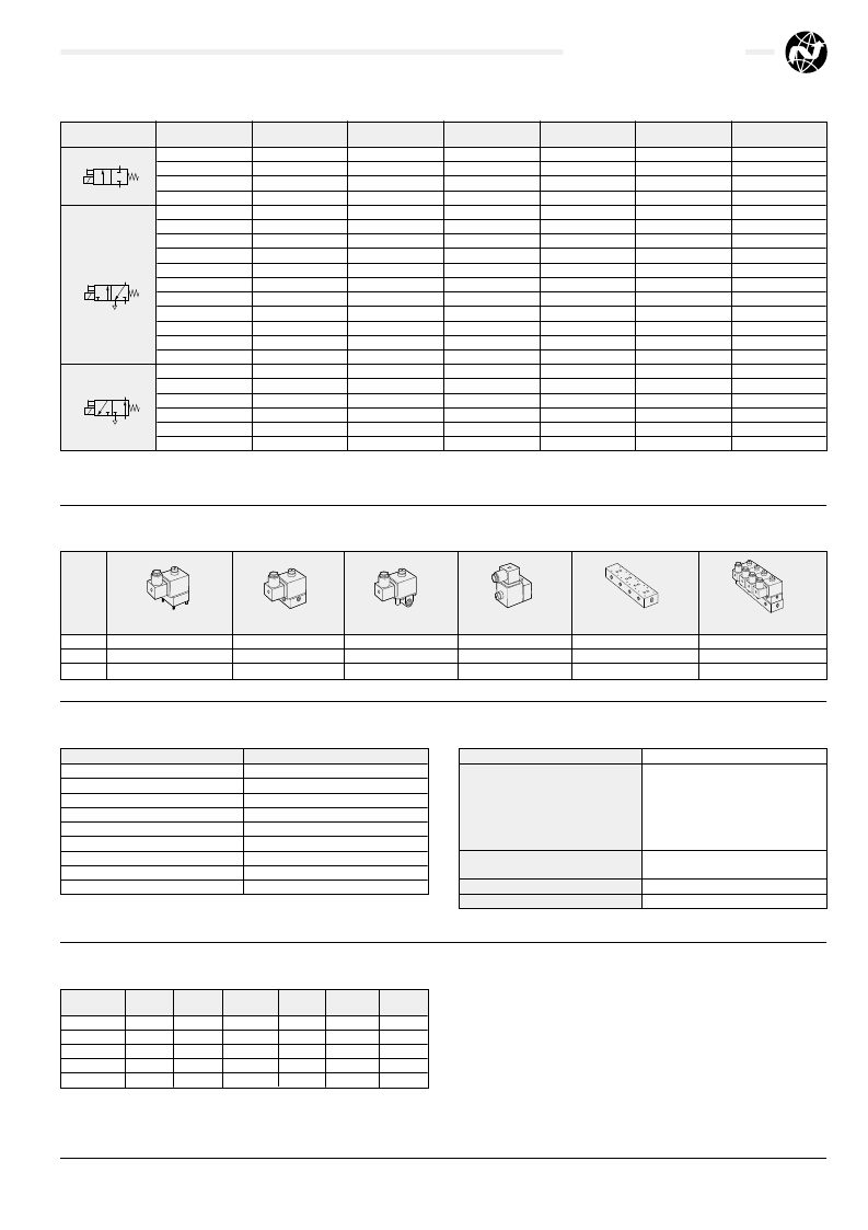
Symbol
Model
Type
Base
Orifice
(mm)
2,5
2,5
2,5
3,0
1,5
2,0
2,5
1,5
2,0
2,5
2,0
2,5
1,5
2,0
2,5
1,5
2,0
2,5
1,5
2,0
2,5
Maximum Operating
Pressure (bar)
16
16
16
13
16
13
10
16
13
10
13
10
16
13
10
16
13
10
16
13
10
Weight
(kg)
0,20
0,24
0,32
0,32
0,20
0,20
0,20
0,24
0,24
0,24
0,24
0,24
0,30
0,30
0,30
0,20
0,20
0,20
0,24
0,24
0,24
Coil Assembly
without plug
V05X286A–Q123*
V05X286A–Q123*
V05X286A–Q123*
V05X286A–Q123*
V05X286A–Q123*
V05X286A–Q123*
V05X286A–Q123*
V05X286A–Q123*
V05X286A–Q123*
V05X286A–Q123*
V05X286A–Q123*
V05X286A–Q123*
V05X286A–Q123*
V05X286A–Q123*
V05X286A–Q123*
V05X286A–Q123*
V05X286A–Q123*
V05X286A–Q123*
V05X286A–Q123*
V05X286A–Q123*
V05X286A–Q123*
V05X286M–B63*A
V05A286M–B63*A
V05B286M–B43*A
V05B286N–B43*A
V05X486K–B63*A
V05X486L–B63*A
V05X486M–B63*A
V05A486K–B63*A
V05A486L–B63*A
V05A486M–B63*A
V05B486L–B43*A
V05B486M–B43*A
V05Y486K–B63*A
V05Y486L–B63*A
V05Y486M–B63*A
V05X386K–B63*A
V05X386L–B63*A
V05X386M–B63*A
V05A386K–B63*A
V05A386L–B63*A
V05A386M–B63*A
Normally Closed
Normally Closed
Normally Closed
Normally Closed
Normally Closed
Normally Closed
Normally Closed
Normally Closed
Normally Closed
Normally Closed
Normally Closed
Normally Closed
Normally Closed
Normally Closed
Normally Closed
Normally Open
Normally Open
Normally Open
Normally Open
Normally Open
Normally Open
Interface
G
1
8
G
1
4
G
1
4
Interface
Interface
Interface
G
1
8
G
1
8
G
1
8
G
1
4
G
1
4
CNOMO
CNOMO
CNOMO
Interface
Interface
Interface
G
1
8
G
1
8
G
1
8
Family
V03
V04
V05
7mm Interface Mounted Valve
V03X
V04X
V05X
G
18
Valve
V03A
V04A
V05A
G
14
Valve
V03B
V04B
V05B
CNOMOMounted Valve
V03Y
V04Y
V05Y
*Insert Voltage Code from table below Insert number of stations
Fixed Length Manifold
M/P35598/
M/P35598/
M/P35598/
Manifold/Valve Assemblies
V03X
86
-H613A#
VO4X
86
-H62*A#
VO5X
86
-H63*A#
Voltage
6 V d.c.
12 V d.c.
24 V d.c.
48 V d.c.
110 V d.c.
24 V 50/60 Hz
48 V 50/60 Hz
110 – 120 V 50/60 Hz
220 – 240 V 50/60 Hz
Codes
1
2
3
5
7
4
6
8
9
4/97
N/ **
5.4.
042.03
V03, V04, V05 Series
Our policy is one of continued research and development. We therefore reserve the right
to amend, without notice, the specifications given in this document.
1
2
12
10
1
12
10
3
2
3
12
10
1
2
V05
*Voltage Codes
*Insert voltage code from Voltage Codes table page
5.4.
042.03.
All models are available without manual override. Change 10th digit to
1
e.g. V03X486J–B
1
1*A.
CNOMO versions are available with a push to operate spring return manual override. Change 10th digit to
3
e.g. V03X486J–B
3
1*A.
Voltage Tolerance:
Inrush/Hold
±10%
V03
VO4
d.c. 1,0 W
d.c. 4,5 W
a.c. 14/10 VA
d.c. 9,0 W
a.c. 27/20 VA
VO5
100% E.D.
A variety of plugs are available, see Section
7.7.001
Screwdriver operated, memory type, standard
IP 65 (DIN 40 050) with terminal box fitted
Plug:
Manual Override
Protection Class:
Note:
The V03 models are only available with the 24 V d.c. coil.
Inlet Orifice
mm
1
1,5
2
2,5
3,0
The above figures are based on valves mounted on a G
1
8
base. They
are typical of all base styles as the orifice diameter is the limiting factor.
C
b
l/min
A
Cv
Kv
0,15
0,30
0,57
0,77
1,16
0,61
0,36
0,30
0,30
0,49
39,4
68,95
137,9
187,15
275,8
0,95
1,26
2,36
3,05
6,25
0,04
0,07
0,14
0,19
0,28
0,03
0,06
0,12
0,16
0,24
Flow Characteristics
Technical Details
Valve and Base Options
相關(guān)PDF資料 |
PDF描述 |
|---|---|
| VO4X286A-Q122212VDC | ELEKTROMAGNET 12VDC |
| VO4X286A-Q122324VDC | ELEKTROMAGNET 24VDC |
| VO4X286A-Q1227110VAC | ELEKTROMAGNET 110VAC |
| VO4X386L-Q116A | VENTIL EXCEL N O OEFFNUNG 2.0MM |
| VO4X486L-Q116A | VENTIL EXCEL 3 2 N V OEFFNUNG 2.0MM |
相關(guān)代理商/技術(shù)參數(shù) |
參數(shù)描述 |
|---|---|
| VO5 | 制造商:Klein Tools Inc 功能描述: |
| VO-500H | 制造商:TALEMA 制造商全稱:TALEMA 功能描述:SMD 10/100Base-TX VoIP Magnetics |
| VO-500J | 制造商:TALEMA 制造商全稱:TALEMA 功能描述:SMD 10/100Base-TX VoIP Magnetics |
| VO610A | 制造商:VISHAY 制造商全稱:Vishay Siliconix 功能描述:Optocoupler, Low Input Current, Phototransistor Output |
| VO610A-1 | 功能描述:晶體管輸出光電耦合器 Phototransistor Out CTR 40-80% RoHS:否 制造商:Vishay Semiconductors 輸入類型:DC 最大集電極/發(fā)射極電壓:70 V 最大集電極/發(fā)射極飽和電壓:0.4 V 絕緣電壓:5300 Vrms 電流傳遞比:100 % to 200 % 最大正向二極管電壓:1.65 V 最大輸入二極管電流:60 mA 最大集電極電流:100 mA 最大功率耗散:100 mW 最大工作溫度:+ 110 C 最小工作溫度:- 55 C 封裝 / 箱體:DIP-4 封裝:Bulk |
發(fā)布緊急采購,3分鐘左右您將得到回復(fù)。