- 您現(xiàn)在的位置:買賣IC網(wǎng) > PDF目錄297787 > VX150 FREQUENZUMRICHTER 3 PHASEN VX 1.5KW PDF資料下載
參數(shù)資料
| 型號(hào): | VX150 |
| 英文描述: | FREQUENZUMRICHTER 3 PHASEN VX 1.5KW |
| 中文描述: | FREQUENZUMRICHTER 3 PHASEN VX的1.5千瓦 |
| 文件頁數(shù): | 2/8頁 |
| 文件大小: | 0K |
| 代理商: | VX150 |
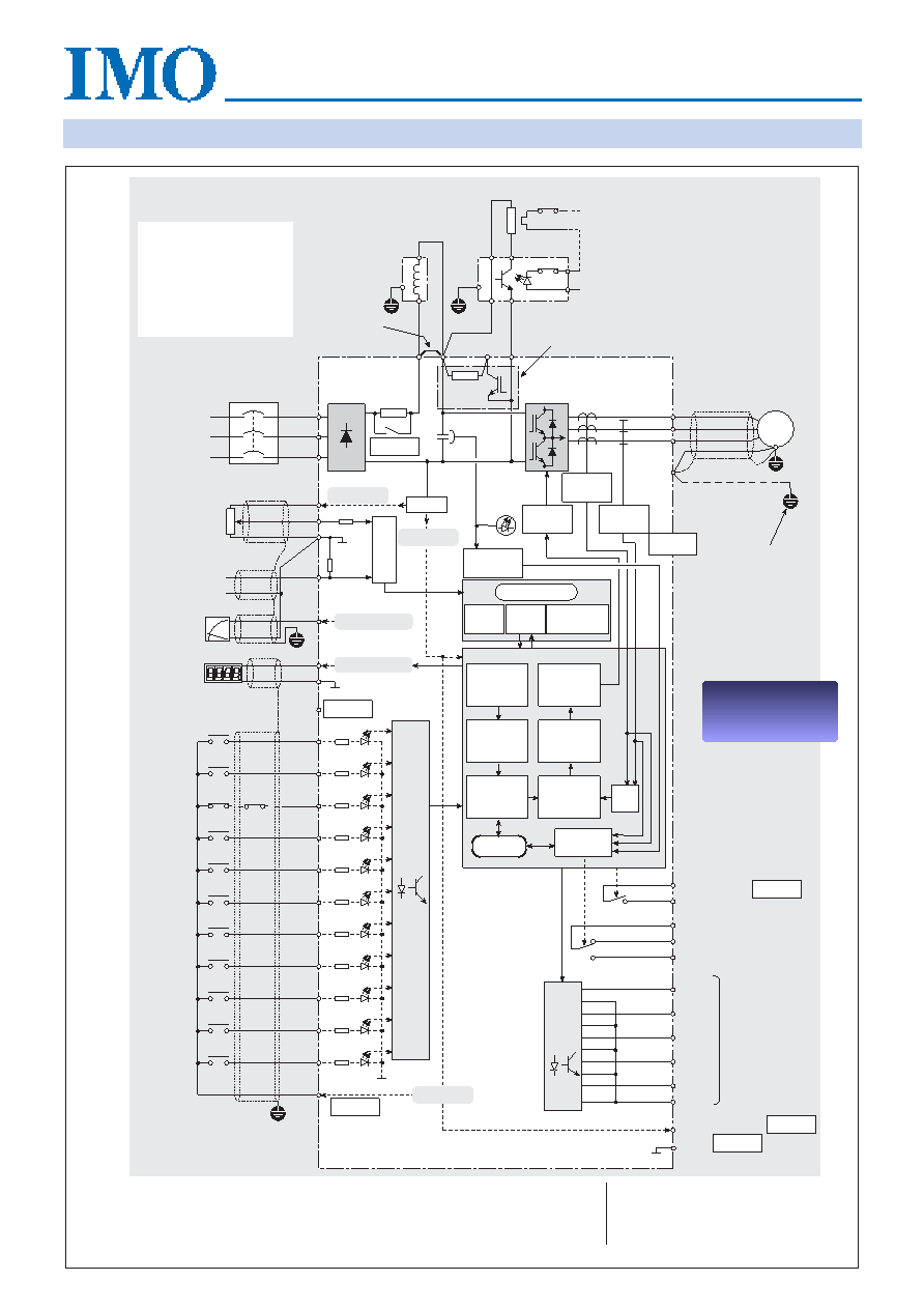
Basic circuit configuration and terminals
Jaguar VX
P1
DC Bus reactor
(Optional
≤22kW)
3-phase
power
supply
50Hz or
60Hz
*
GND
(PE)
2
1
M
Link P1 to (*)
if DC reactor
not required
Braking resistor (option)
for all inverters.
Braking unit (option).
Applicable to VX1100, VX1500P, VX30K
and inverters larger than these.
On-board braking IGBT and resistor applicable
only to VX40 to VX750 and VX750P to VX1100P.
Disconnect the internal resistor (R) before
connecting an external resistor.
*
U
V
W
L1
L2
L3
(13)
(12)
(11)
Z
0V
Analog voltage
frequency ref.
input
(Pot. 1k
, 1W)
(C1)
250
Power
charge
LED
‘CRG’
(FMA)
4-20mA
analog input
+10V DC
0 to 10V DC
(FWD)
BU
RTS
(REV)
(THR)
BU
RTS
12
(CM)
(X1)
(HLD)
4.7k
(X2)
(X3)
(X4)
(X5)
(BX)
(RST)
(P24) or (CMS)
Programmable
analog
output
Connect via
RF filter (if fitted)
(Y5E)
(CMC)
(Y4E)
(Y3E)
(Y2E)
(Y1E)
(30A)
(30B)
(30C) Trip
relay
output
Programmable
outputs
Control
inputs
DC voltage
detection
Gate
drive
Keys
LED, LCD
displays
CPU
A/D
Input
signal
PWM
generator
Auto-
voltage
regulator
Accel /
Decel
regulator
A/D
Function
generator
Frequency
command
switch
NOTES
CPU
Keypad Panel
GND
(PE)
(P24) or (CMS)
Digital
output
(FMP)
Pulse output
Input
contactor
+ve
GND
(PE)
0V
(CM)
0V
For inverters rated
≤22kW the inrush contactor is replaced by an SCR.
Voltage detection circuit applicable for inverters
≥30kW only.
Standard for inverters
≥30kW, optional for smaller models.
Two terminals (CM) standard for inverters
≤22kW, one for ≥30kW.
If motor thermistors are required, please consult IMO.
Internal +24V DC supply terminal designated P24 (
≤22kW) or CMS (≥30kW).
(AX2)
(AX1) Run
relay
output
SMPS
+24V DC
4.7k
4.7k
4.7k
4.7k
4.7k
4.7k
4.7k
4.7k
4.7k
4.7k
0V
+24V DC
(V1)
Note (2)
Note (3)
Output
signal
Note (3)
Torque
vector
calculator
Protective
logic
Note (4)
Note (1)
0V Common Terminals (11) and
(CM) are optically isolated.
Relay status shown as at inverter
‘power ON’ or ‘healthy’.
(1)
(2)
(3)
(4)
(5)
(6)
24V
0V
Earth busbar
at MCC
Terminal Markings for DC
bus reactor and Braking
Resistor or Braking Unit
The marking of these
terminals varies between
different sizes of Jaguar VX
inverter. Please refer to
pages 19, 20 and 21 for
specific detail.
*
P(+)
RTS = Volt-free NC contact
for thermal protection.
R
N(-)
P(+)
DB
Voltage
detection
Current
detection
Note (6)
WARNING! INVERTER MUST
BE EARTHED
Terminal Markings for DC
bus reactor and Braking
Resistor for Braking Unit
The marking of these
terminals varies between
different sizes of Jaguar VX
inverter. Please refer to
manual for specific details.
PRICE
INFORMATION
AND ORDERING
PRICE
INFORMATION
AND ORDERING
相關(guān)PDF資料 |
PDF描述 |
|---|---|
| VX1500 | FREQUENZUMRICHTER 3 PHASEN VX 15KW |
| VX1500P | FREQUENZUMRICHTER 3 PHASEN VXP 15KW |
| VX1301-1 | ABISOLIERWERKZEUG MIT EINSATZ 3 STUFEN |
| VXO65HG1I3I8.00MHZ | Peripheral IC |
| VXS150-1 | FREQUENZUMRICHTER 1 PHASE 1.5KW |
相關(guān)代理商/技術(shù)參數(shù) |
參數(shù)描述 |
|---|---|
| VX16S00B-6ZZXX-1XX-XHD3 | 制造商:Carling Technologies 功能描述:V-SERIES ROCKER SWITCH - Bulk |
| VX-189 | 制造商:VECTRON 制造商全稱:Vectron International, Inc 功能描述:Hi-Reliability Voltage Controlled Crystal Oscillator |
| VX1A | 功能描述:基本/快動(dòng)開關(guān) COMM SOLID STATE/MAG RoHS:否 制造商:Omron Electronics 觸點(diǎn)形式:SPDT 執(zhí)行器:Lever 電流額定值:5 A 電壓額定值 AC:250 V 電壓額定值 DC:30 V 功率額定值: 工作力:120 g IP 等級(jí):IP 67 NEMA 額定值: 端接類型:Wire 安裝:Panel |
| VX1A01 | 制造商:HONEYWELL 功能描述:Magnetic Sensors 制造商:Honeywell Sensing and Control 功能描述:Magnetic Sensors |
| VX1A-01 | 功能描述:CONNECTOR FOR VX SERIES SNAP RoHS:是 類別:開關(guān) >> 配件 系列:- 標(biāo)準(zhǔn)包裝:100 系列:- 其它名稱:886.0007886.0007-ND |
發(fā)布緊急采購,3分鐘左右您將得到回復(fù)。