- 您現(xiàn)在的位置:買賣IC網(wǎng) > PDF目錄361773 > W24010-70LI x8 SRAM PDF資料下載
參數(shù)資料
| 型號(hào): | W24010-70LI |
| 英文描述: | x8 SRAM |
| 中文描述: | x8的SRAM |
| 文件頁數(shù): | 3/11頁 |
| 文件大小: | 216K |
| 代理商: | W24010-70LI |
W24010
Publication Release Date: November 1998
- 3 -
Revision A6
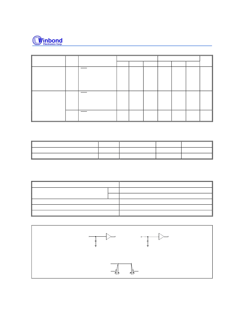
Operating Characteristics, continued
PARAMETER
SYM.
TEST CONDITIONS
5V
3V
UNIT
MIN.
-
TYP.*
-
MAX.
70
MIN.
-
TYP.*
-
MAX.
30
Operating Power
Supply Current
I
DD
CS1
= V
IL
(max.)
and CS2 = V
IH
(min.)
I/O = 0 mA
Cycle = min.
Duty = 100%
mA
Standby Power
Supply Current
I
SB
CS1
= V
IH
(min.) or
CS2 = V
IL
(max.)
Cycle = min.
Duty = 100%
CS1
≥
V
DD
-0.2V or
CS2
≤
0.2V
-
-
3
-
-
1
mA
I
SB
1
-
1.0
10
-
0.5
5
μ
A
Note: Typical parameter is measured under ambient temperature T
A
= 25
°
C and V
DD
= 5V/ 3V
CAPACITANCE
(V
DD
= 5 V, T
A
= 25
°
C, f = 1 MHz)
PARAMETER
Input Capacitance
Input/Output Capacitance
SYM.
C
IN
C
I/O
CONDITIONS
V
IN
= 0V
V
OUT
= 0V
MAX.
6
8
UNIT
pF
pF
Note: These parameters are sampled but not 100% tested.
AC Characteristics
AC Test Conditions
PARAMETER
CONDITIONS
Input Pulse Levels
3V
5V
0V to 2.4V
0V to 3.0V
5 nS
1.5V
See the drawing below
Input Rise and Fall Times
Input and Output Timing Reference Level
Output Load
AC Test Loads and Waveform
90%
90%
5 nS
10%
5 nS
10%
OUTPUT
OUTPUT
2.4 V / 3.0 V
0 V
100 pF
Including
Jig and
Scope
5 pF
Including
Jig and
Scope
1 TTL
1 TTL
CLZ,
OLZ,
T
CHZ, OHZ,
T
WHZ, OW
T
(For T
)
相關(guān)PDF資料 |
PDF描述 |
|---|---|
| W24010-70SL | x8 SRAM |
| W24010Q-70LE | x8 SRAM |
| W24010Q-70LI | x8 SRAM |
| W24010Q-70SL | x8 SRAM |
| W24010S-70LE | x8 SRAM |
相關(guān)代理商/技術(shù)參數(shù) |
參數(shù)描述 |
|---|---|
| W24010-70SL | 制造商:未知廠家 制造商全稱:未知廠家 功能描述:x8 SRAM |
| W24010Q-70LE | 制造商:未知廠家 制造商全稱:未知廠家 功能描述:x8 SRAM |
| W24010Q-70LI | 制造商:未知廠家 制造商全稱:未知廠家 功能描述:x8 SRAM |
| W24010Q-70SL | 制造商:未知廠家 制造商全稱:未知廠家 功能描述:x8 SRAM |
| W24010S-70LE | 制造商:未知廠家 制造商全稱:未知廠家 功能描述:x8 SRAM |
發(fā)布緊急采購,3分鐘左右您將得到回復(fù)。