- 您現(xiàn)在的位置:買賣IC網(wǎng) > PDF目錄68747 > W33D4021 (WINBOND ELECTRONICS CORP) LIQUID CRYSTAL DISPLAY DRIVER, PQFP64 PDF資料下載
參數(shù)資料
| 型號(hào): | W33D4021 |
| 廠商: | WINBOND ELECTRONICS CORP |
| 元件分類: | 顯示驅(qū)動(dòng)器 |
| 英文描述: | LIQUID CRYSTAL DISPLAY DRIVER, PQFP64 |
| 封裝: | PLASTIC, QFP-64 |
| 文件頁數(shù): | 25/28頁 |
| 文件大小: | 305K |
| 代理商: | W33D4021 |
第1頁第2頁第3頁第4頁第5頁第6頁第7頁第8頁第9頁第10頁第11頁第12頁第13頁第14頁第15頁第16頁第17頁第18頁第19頁第20頁第21頁第22頁第23頁第24頁當(dāng)前第25頁第26頁第27頁第28頁
W33D0001 SERIES
- 6 -
FUNCTIONAL DESCRIPTION
1. Operating Mode
The W33D0001 provides three operating modes: Normal mode, Clock mode, and Timer mode.
Only the normal mode and clock mode can be programmed by the
P. The address data
corresponding to the mode is shown in Figure 1.
In Figure 1 the address 0
127 range works as a working-loop. This means that the programmed
address located in the 0-127 range will return to zero when the 127 address location is exceeded. The
128
255 range has the same function as the 0127 range.
Data in the 0
127 range are known as normal mode data. Data in the 192227 range are known as
clock mode data, and data in the 248
255 are known as function control bits.
The following description shows the control functions, including the 8 control bits (248
255), the
transceiver function controlled by a
P in normal mode (0127), and clock mode (192227).
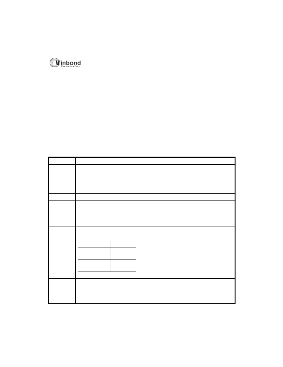
1.1 The Function Control Bits
BIT
FUNCTION
0
127
These addresses are for normal mode data display. This section functions as a
working-loop. When you program data over address 127, the data will automatically
start from the 0 address again.
128
191,
228
247
Reserved section area.
192
227
Clock data area.
248
Waveform Disable bit
0: Disable the waveform output from the WFG pin and keep the output to high.
(Default value)
1: Enable the waveform output from the WFG pin.
249, 250
Determine which waveform will be generated on the WFG pin.
The waveform can be determined by the following table:
249
250
Divid Time
00
01
1
0
1
1S (default)
1/2
1/16
1/256
251
LCD panel ON/OFF control bit.
(This bit will not affect the normal data in the chip, it just affects the LCD panel)
0: LCD panel light on. (Default value)
1: LCD panel light off.
相關(guān)PDF資料 |
PDF描述 |
|---|---|
| W33D4031 | LIQUID CRYSTAL DISPLAY DRIVER, PQFP64 |
| W33D4041 | LIQUID CRYSTAL DISPLAY DRIVER, PQFP64 |
| W33D4111 | LIQUID CRYSTAL DISPLAY DRIVER, PQFP64 |
| W33D4121 | LIQUID CRYSTAL DISPLAY DRIVER, PQFP64 |
| W33D4131 | LIQUID CRYSTAL DISPLAY DRIVER, PQFP64 |
相關(guān)代理商/技術(shù)參數(shù) |
參數(shù)描述 |
|---|---|
| W33FX-22 | 制造商:Magnecraft 功能描述: |
| W33HSX-178 | 制造商:Struthers-Dunn 功能描述: |
| W33HSX-179 | 制造商:Struthers-Dunn 功能描述: |
| W33HSX-182 | 制造商:Struthers-Dunn 功能描述: |
| W33HSX-183 | 制造商:Magnecraft 功能描述: |
發(fā)布緊急采購(gòu),3分鐘左右您將得到回復(fù)。