- 您現(xiàn)在的位置:買賣IC網(wǎng) > PDF目錄361793 > W78E51-40 8-BIT MICROCONTROLLER PDF資料下載
參數(shù)資料
| 型號(hào): | W78E51-40 |
| 元件分類: | 8位微控制器 |
| 英文描述: | 8-BIT MICROCONTROLLER |
| 中文描述: | 8位微控制器 |
| 文件頁數(shù): | 21/22頁 |
| 文件大小: | 306K |
| 代理商: | W78E51-40 |
Preliminary W78E52B
Publication Release Date: December 1998
- 21 -
Revision A1
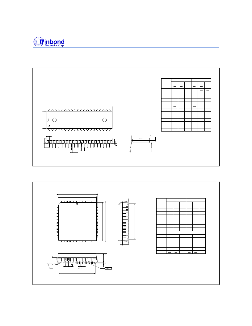
PACKAGE DIMENSIONS
40-pin DIP
Seating Plane
1. Dimension D Max. & S include mold flash or
tie bar burrs.
2. Dimension E1 does not include interlead flash.
3. Dimension D & E1 includ.
are determined at the mold parting line.
4. Dimension B1 does not include dambar
6. General appearance spec. should be based on
final visual inspection spec.
1.372
1.219
0.054
0.048
Notes:
Symbol
Min.
Nom.
Max.
Max.
Nom.
Min.
Dimension in inch
Dimension in mm
0.050
1.27
0.210
5.334
0.010
0.150
0.016
0.155
0.018
0.160
0.022
3.81
0.406
0.254
3.937
0.457
4.064
0.559
0.008
0.120
0.670
0.010
0.130
0.014
0.140
0.203
3.048
0.254
3.302
0.356
3.556
0.540
0.550
0.545
13.72
13.97
13.84
17.01
15.24
14.986
15.494
0.600
0.590
0.610
2.286
2.54
2.794
0.090
0.100
0.110
A
A
A
B
B
1
c
D
E
E
1
e
L
a
A
S
1
2
1
e
2.055
2.070
52.20
52.58
0
15
0.090
2.286
0.650
0.630
16.00
16.51
protrusion/intrusion.
5. Controlling dimension: Inches.
15
0
e
A
A
a
c
E
Base Plane
1
A
1
e
L
A
S
1
E
D
1
B
B
40
21
20
1
2
44-pin PLCC
44
40
39
29
28
18
17
7
6
1
L
c
1
b
2
A
H
D
D
e
b
E
H
E
y
A
A
1
Seating Plane
D
G
G
E
Symbol
Min. Nom.
Max.
Max.
Nom.
Min.
Dimension in inch
Dimension in mm
A
A
A
b
1
e
G
D
H
E
L
y
b
c
D
E
1
2
H
D
G
E
Notes:
1. Dimension D & E do not include interlead
on final visual inspection spec.
4. General appearance spec. should be based
3. Controlling dimension: Inches
protrusion/intrusion.
2. Dimension b1 does not include dambar
flash.
0.020
0.145
0.026
0.016
0.008
0.648
0.590
0.680
0.090
0.150
0.028
0.018
0.010
0.653
0.610
0.690
0.100
0.050
BSC
0.185
0.155
0.032
0.022
0.014
0.658
0.630
0.700
0.110
0.004
0.508
3.683
0.66
0.406
0.203
16.46
14.99
17.27
2.296
3.81
0.711
0.457
0.254
16.59
15.49
17.53
2.54
1.27
4.699
3.937
0.813
0.559
0.356
16.71
16.00
17.78
2.794
0.10
BSC
16.71
16.59
16.46
0.658
0.653
0.648
16.00
15.49
14.99
0.630
0.610
0.590
17.78
17.53
17.27
0.700
0.690
0.680
θ
相關(guān)PDF資料 |
PDF描述 |
|---|---|
| W78E52BF-40 | 8-BIT MTP MICROCONTROLLER |
| W78E52BP-24 | 8-BIT MTP MICROCONTROLLER |
| W78E52BP-40 | 8-BIT MTP MICROCONTROLLER |
| W78E52B | 8-BIT MTP Monitor Microcontroller(多次可編程的8位的監(jiān)視微控制器) |
| W78E52BF-24 | 8-BIT MTP MICROCONTROLLER |
相關(guān)代理商/技術(shù)參數(shù) |
參數(shù)描述 |
|---|---|
| W78E516 | 制造商:WINBOND 制造商全稱:Winbond 功能描述:8-BIT MICROCONTROLLER |
| W78E516B | 制造商:WINBOND 制造商全稱:Winbond 功能描述:8-BIT MICROCONTROLLER |
| W78E516B_06 | 制造商:WINBOND 制造商全稱:Winbond 功能描述:8-BIT MICROCONTROLLER |
| W78E516B-24 | 制造商:WINBOND 制造商全稱:Winbond 功能描述:8-BIT MICROCONTROLLER |
| W78E516B-40 | 制造商:WINBOND 制造商全稱:Winbond 功能描述:8-BIT MICROCONTROLLER |
發(fā)布緊急采購,3分鐘左右您將得到回復(fù)。