- 您現(xiàn)在的位置:買賣IC網(wǎng) > PDF目錄361792 > W78E51P-16 8-BIT MICROCONTROLLER PDF資料下載
參數(shù)資料
| 型號: | W78E51P-16 |
| 元件分類: | 8位微控制器 |
| 英文描述: | 8-BIT MICROCONTROLLER |
| 中文描述: | 8位微控制器 |
| 文件頁數(shù): | 14/22頁 |
| 文件大小: | 306K |
| 代理商: | W78E51P-16 |
Preliminary W78E52B
- 14 -
AC CHARACTERISTICS
The AC specifications are a function of the particular process used to manufacture the part, the
ratings of the I/O buffers, the capacitive load, and the internal routing capacitance. Most of the
specifications can be expressed in terms of multiple input clock periods (T
CP
), and actual parts will
usually experience less than a
±
20 nS variation. The numbers below represent the performance
expected from a 0.6micron CMOS process when using 2 and 4 mA output buffers.
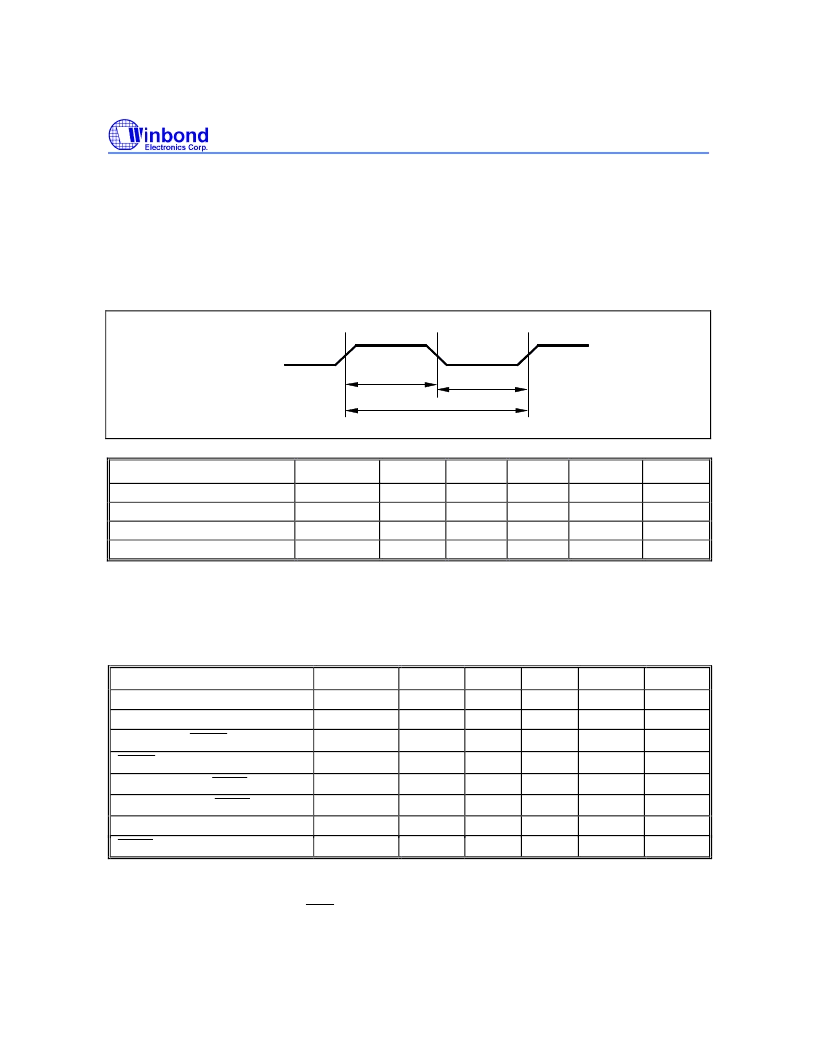
Clock Input Waveform
T
T
XTAL1
F
CH
CL
OP,
T
CP
PARAMETER
SYMBOL
F
OP
T
CP
T
CH
T
CL
MIN.
0
25
10
10
TYP.
-
-
-
-
MAX.
40
-
-
-
UNIT
MHz
nS
nS
nS
NOTES
1
2
3
3
Operating Speed
Clock Period
Clock High
Clock Low
Notes:
1. The clock may be stopped indefinitely in either state.
2. The T
CP
specification is used as a reference in other specifications.
3. There are no duty cycle requirements on the XTAL1 input.
Program Fetch Cycle
PARAMETER
SYMBOL
T
AAS
T
AAH
T
APL
T
PDA
T
PDH
T
PDZ
T
ALW
T
PSW
MIN.
1 T
CP
-
1 T
CP
-
1 T
CP
-
-
0
0
2 T
CP
-
3 T
CP
-
TYP.
-
-
-
-
-
-
2 T
CP
3 T
CP
MAX.
-
-
-
2 T
CP
1 T
CP
1 T
CP
-
-
UNIT
nS
nS
nS
nS
nS
nS
nS
nS
NOTES
4
1, 4
4
2
3
Address Valid to ALE Low
Address Hold from ALE Low
ALE Low to
PSEN
Low
PSEN
Low to Data Valid
Data Hold after PSEN High
Data Float after PSEN High
ALE Pulse Width
PSEN Pulse Width
4
4
Notes:
1. P0.0
P0.7, P2.0
P2.7 remain stable throughout entire memory cycle.
2. Memory access time is 3 T
CP
.
3. Data have been latched internally prior to PSEN going high.
4. "
" (due to buffer driving delay and wire loading) is 20 nS.
相關(guān)PDF資料 |
PDF描述 |
|---|---|
| W78E51P-24 | 8-BIT MICROCONTROLLER |
| W78E51P-33 | 8-BIT MICROCONTROLLER |
| W78E51P-40 | 8-BIT MICROCONTROLLER |
| W78E52-16 | 8-BIT MICROCONTROLLER |
| W78E52-24 | 8-BIT MICROCONTROLLER |
相關(guān)代理商/技術(shù)參數(shù) |
參數(shù)描述 |
|---|---|
| W78E51P-24 | 制造商:未知廠家 制造商全稱:未知廠家 功能描述:8-Bit Microcontroller |
| W78E51P-33 | 制造商:未知廠家 制造商全稱:未知廠家 功能描述:8-Bit Microcontroller |
| W78E51P-40 | 制造商:未知廠家 制造商全稱:未知廠家 功能描述:8-Bit Microcontroller |
| W78E52-16 | 制造商:未知廠家 制造商全稱:未知廠家 功能描述:8-Bit Microcontroller |
| W78E52-24 | 制造商:未知廠家 制造商全稱:未知廠家 功能描述:8-Bit Microcontroller |
發(fā)布緊急采購,3分鐘左右您將得到回復(fù)。