- 您現(xiàn)在的位置:買賣IC網(wǎng) > PDF目錄361798 > W91F843AN Telecommunication IC PDF資料下載
參數(shù)資料
| 型號(hào): | W91F843AN |
| 英文描述: | Telecommunication IC |
| 中文描述: | 通信集成電路 |
| 文件頁(yè)數(shù): | 3/26頁(yè) |
| 文件大小: | 221K |
| 代理商: | W91F843AN |
第1頁(yè)第2頁(yè)當(dāng)前第3頁(yè)第4頁(yè)第5頁(yè)第6頁(yè)第7頁(yè)第8頁(yè)第9頁(yè)第10頁(yè)第11頁(yè)第12頁(yè)第13頁(yè)第14頁(yè)第15頁(yè)第16頁(yè)第17頁(yè)第18頁(yè)第19頁(yè)第20頁(yè)第21頁(yè)第22頁(yè)第23頁(yè)第24頁(yè)第25頁(yè)第26頁(yè)
W91F810N SERIES
Publication Release Date: March 2000
- 3 -
Revision A2
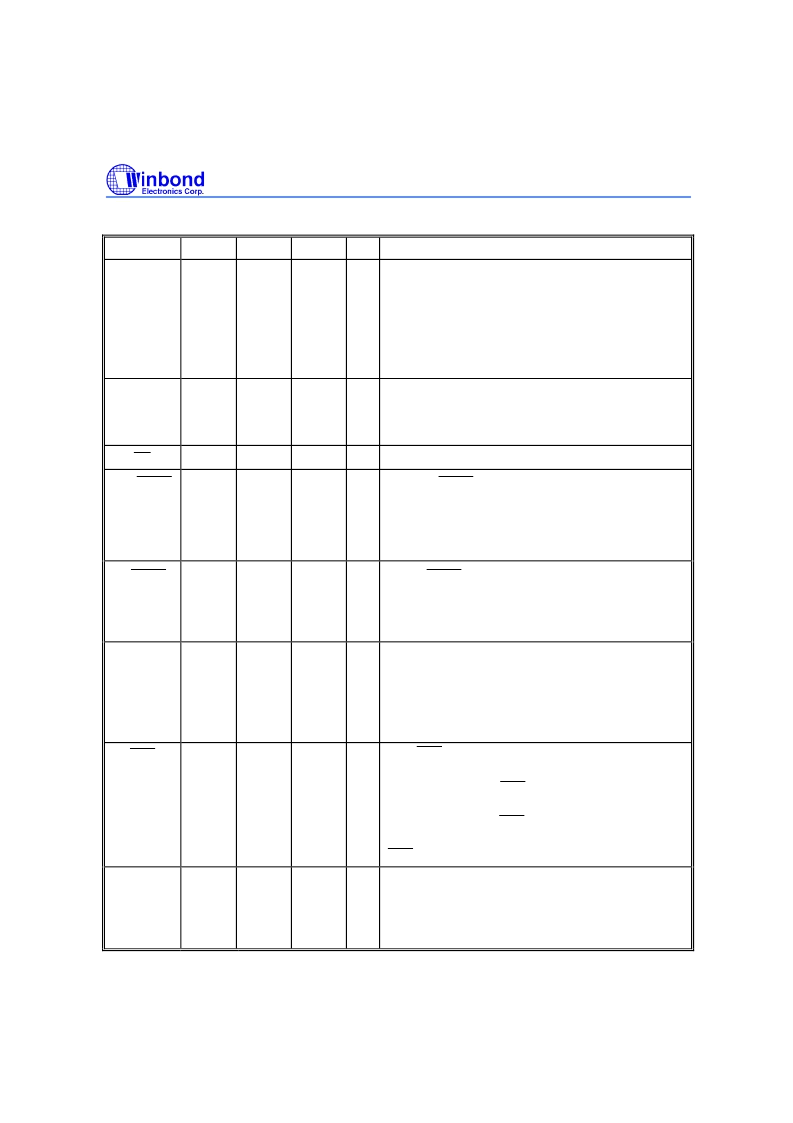
PIN DESCRIPTION
SYMBOL
22-PIN 24-PIN 28-PIN
I/O
FUNCTION
Column-
Row
Inputs
1
5
&
18
22
1
5
&
20
24
1
6
&
23
28
I
The keyboard input is compatible with a standard 6
×
6 or 7
×
7 keyboard, an inexpensive single
contact (Form A) keyboard, and electronic input.
In normal operation, any single button can be
pushed to produce dual tone, pulses, or functions.
Activation of two or more buttons will result in no
response except for a single tone.
XT
9
9
10
I
A built-in inverter together with an inexpensive
3.579545 MHz crystal supplies the oscillator. The
oscillator stops when there is no keypad input. The
crystal frequency deviation is 0.02%.
XT
10
10
11
O
Crystal oscillator output pin.
T/P
MUTE
11
11
12
O
The T/P
MUTE
is a conventional CMOS N-channel
open drain output.
The output transistor turns on with a low level
during a dialing sequence (both pulse and tone
mode). Otherwise, it is off.
K
MUTE
17
19
22
O
The K
MUTE
is a conventional CMOS N-channel
open drain output.
Toggle action speech mute control pin by MUTE
key.
Connecting the mode pin to V
SS
places the dialer
in tone mode.
Connecting the mode pin to V
DD
places the dialer
in pulse mode with an M/B ratio of 40:60.
Leaving the mode pin floating places the dialer in
pulse mode with an M/B ratio of 33.3:66.7.
The
HKS
(hook switch) input is used to sense
whether the handset is on-hook or off-hook.
In on-hook state, HKS = 1: chip is in sleeping
mode, no operation.
In off-hook state,
HKS
= 0: chip is enabled for
normal operation.
HKS
pin is pulled to V
DD
by internal resistor.
The key tone output is a conventional CMOS
inverter. The key tone is generated when any valid
key is pressed; the KT pin generates a 1.2 KHz
square wave at 35 mS. When no key is pressed,
the KT pin remains in low state.
MODE
15
17
20
I
HKS
12
14
17
I
KT
(W91F810N/F8
10AN/F812N/F
812AN/F811AN
/F813AN only)
6
6
7
O
相關(guān)PDF資料 |
PDF描述 |
|---|---|
| W91F811ALN | 23-FLASH MEMORY TONE/PULSE DIALER WITH HANDFREE, LOCK AND HOLD FUNCTIONS |
| W91F811AN | 23-FLASH MEMORY TONE/PULSE DIALER WITH HANDFREE, LOCK AND HOLD FUNCTIONS |
| W91F812AN | 23-FLASH MEMORY TONE/PULSE DIALER WITH HANDFREE, LOCK AND HOLD FUNCTIONS |
| W91F812N | POT 200 OHM 6MM RD CERM ST |
| W91F813AN | 23-FLASH MEMORY TONE/PULSE DIALER WITH HANDFREE, LOCK AND HOLD FUNCTIONS |
相關(guān)代理商/技術(shù)參數(shù) |
參數(shù)描述 |
|---|---|
| W91S1A22-240 | 制造商:Magnecraft 功能描述: |
| W91S1D22-12 | 制造商:Magnecraft 功能描述: |
| W91S1D22-24 | 制造商:Magnecraft 功能描述: |
| W91S1D3224 | 制造商:Magnecraft 功能描述:3-5 Days |
| W91S1D32-24 | 制造商:Magnecraft 功能描述: |
發(fā)布緊急采購(gòu),3分鐘左右您將得到回復(fù)。