- 您現(xiàn)在的位置:買賣IC網(wǎng) > PDF目錄361799 > W9966TF PDF資料下載
參數(shù)資料
| 型號(hào): | W9966TF |
| 文件頁(yè)數(shù): | 17/44頁(yè) |
| 文件大?。?/td> | 278K |
| 代理商: | W9966TF |
第1頁(yè)第2頁(yè)第3頁(yè)第4頁(yè)第5頁(yè)第6頁(yè)第7頁(yè)第8頁(yè)第9頁(yè)第10頁(yè)第11頁(yè)第12頁(yè)第13頁(yè)第14頁(yè)第15頁(yè)第16頁(yè)當(dāng)前第17頁(yè)第18頁(yè)第19頁(yè)第20頁(yè)第21頁(yè)第22頁(yè)第23頁(yè)第24頁(yè)第25頁(yè)第26頁(yè)第27頁(yè)第28頁(yè)第29頁(yè)第30頁(yè)第31頁(yè)第32頁(yè)第33頁(yè)第34頁(yè)第35頁(yè)第36頁(yè)第37頁(yè)第38頁(yè)第39頁(yè)第40頁(yè)第41頁(yè)第42頁(yè)第43頁(yè)第44頁(yè)

Prel i m nary -17- November 1997
W9966CF/TF
Video Camera Interface Controller with Compression
7.3.2Device ID
The Device ID is a length field followed by a string of ASCII characters defining W9966CF/TF
characteristics and capabilities. The Device ID will be sent from the W9966CF/TF to the host using
the Nibble Mode, which is required by the P1284.
The W9966CF/TF Device ID contains four keys: MANUFACTURER, MODEL, CLASS, and
DESCRIPTION. Currently implemented ID string is shown below, which may be modified depending
on individual vendor
′
s need.
x
′
00
′
, x
′
60
′
,
MFG:Winbond;
MDL:SA5459;
CLS:DIGCAM;
DES:Winbond
′
s DIGCAM driver can not be found in the system;
7.3.3Device Addressing
The bi-directional SPP/EPP/ECP protocal describes two basic types of 8-bit information transfers:
data read/write operations and address read/write operations. Table 7.4 specifies the control signals
used by each mode to perform address/data cycle and to indicate reverse data flow.
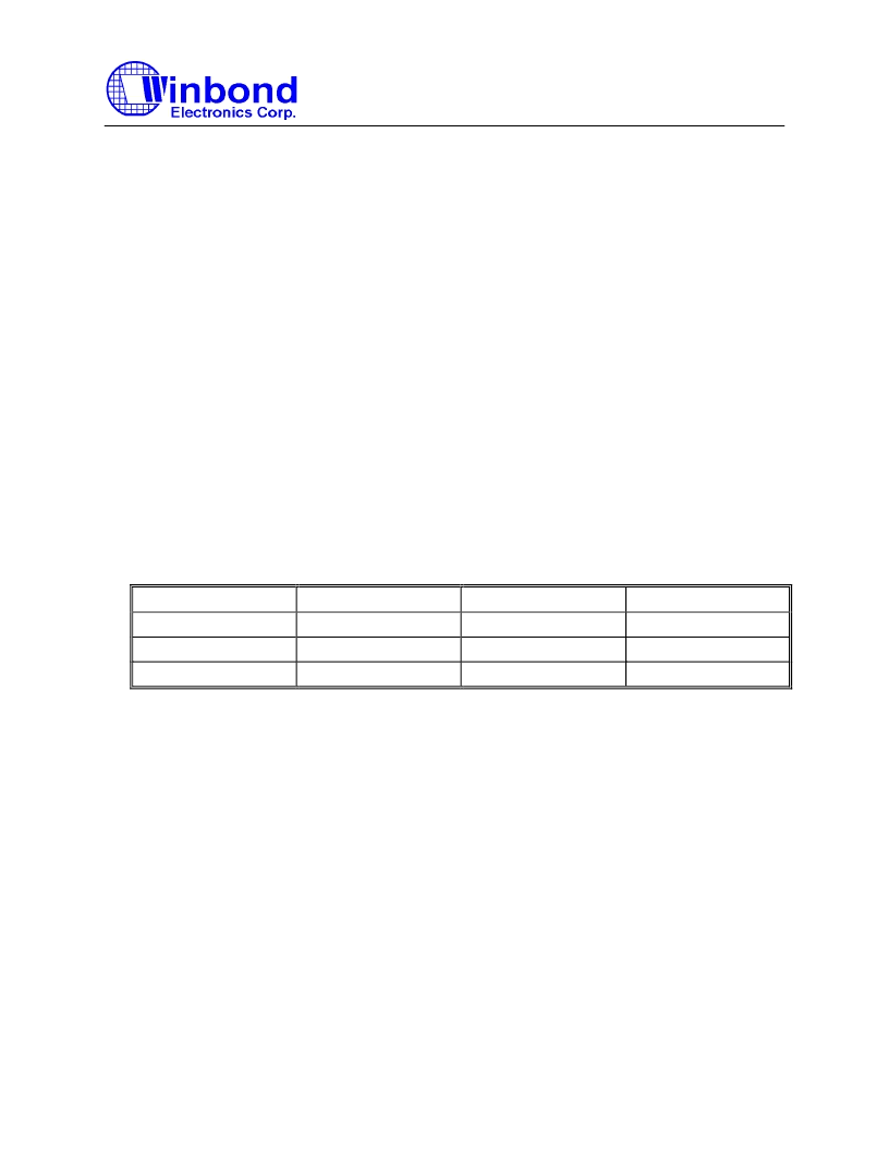
TABLE 7.4 PARALLEL PORT READ/WRITE SIGNALS
SIGNAL
SPP
EPP
ECP
Address Strobe
NSTB (NAFD=0)
NSLCT
NSTB (NAFD=0)
Data Strobe
NSTB (NAFD=1)
NAFD
NSTB (NAFD=1)
Reverse Channel
Not supported
Implicit
NINIT=0
An address write cycle is used to select the W9966CF/TF
′
s address mode for subsequent data cycles.
Figure 7.3 defines the data bits of this parallel port data path during an address write operation to the
W9966CF/TF.
Three kinds of output format are provided:
CCD Raw Data :
used only when input data is the CCD raw data (CR01_1 = 0).
YUV 4:2:2 :
used when input data is in 16-bit YUV 4:2:2 format (CR01_1 = 1).
YUV 4:2:0 :
used when input data is in 16-bit YUV 4:2:2 format (CR01_1 = 1).
CCD Raw Data format is supported only in the Original Transfer Mode, while YUV 4:2:2 and YUV
4:2:0 formats are both supported in either Original Transfer Mode or Compressed Transfer Mode.
相關(guān)PDF資料 |
PDF描述 |
|---|---|
| W9966TF | Video Camera Interface Controller With Compression(運(yùn)用壓縮技術(shù)的攝像照相機(jī)接口控制器) |
| W9966CF | Video Camera Interface Controller With Compression(運(yùn)用壓縮技術(shù)的攝像照相機(jī)接口控制器) |
| W9968CF | Digital Camera |
| W9N150V | N-channel 1500V - 2.2ヘ - 8A - TO-247 Very high voltage PowerMESH⑩ Power MOSFET |
| WA-A240PAI | Peripheral Interface |
相關(guān)代理商/技術(shù)參數(shù) |
參數(shù)描述 |
|---|---|
| W99681CF | 制造商:WINBOND 制造商全稱:Winbond 功能描述:JPEG USB Dual Mode Camera Chip |
| W99685 | 制造商:未知廠家 制造商全稱:未知廠家 功能描述: |
| W99685BS | 制造商:WINBOND 制造商全稱:Winbond 功能描述:SYSTEM CAMERA DEVICE |
| W99685FS | 制造商:WINBOND 制造商全稱:Winbond 功能描述:SYSTEM CAMERA DEVICE |
| W9968CF | 制造商:未知廠家 制造商全稱:未知廠家 功能描述:Digital Camera |
發(fā)布緊急采購(gòu),3分鐘左右您將得到回復(fù)。