- 您現(xiàn)在的位置:買(mǎi)賣(mài)IC網(wǎng) > PDF目錄140428 > WEDPN8M64V-133B2I (MICROSEMI CORP-PMG MICROELECTRONICS) 8M X 64 SYNCHRONOUS DRAM, 5.5 ns, PBGA219 PDF資料下載
參數(shù)資料
| 型號(hào): | WEDPN8M64V-133B2I |
| 廠商: | MICROSEMI CORP-PMG MICROELECTRONICS |
| 元件分類(lèi): | DRAM |
| 英文描述: | 8M X 64 SYNCHRONOUS DRAM, 5.5 ns, PBGA219 |
| 封裝: | 21 X 21 MM, PLASTIC, BGA-219 |
| 文件頁(yè)數(shù): | 2/15頁(yè) |
| 文件大小: | 398K |
| 代理商: | WEDPN8M64V-133B2I |
第1頁(yè)當(dāng)前第2頁(yè)第3頁(yè)第4頁(yè)第5頁(yè)第6頁(yè)第7頁(yè)第8頁(yè)第9頁(yè)第10頁(yè)第11頁(yè)第12頁(yè)第13頁(yè)第14頁(yè)第15頁(yè)
WEDPN8M64V-XB2X
10
White Electronic Designs Corporation (602) 437-1520 www.whiteedc.com
White Electronic Designs
January 2005
Rev. 2
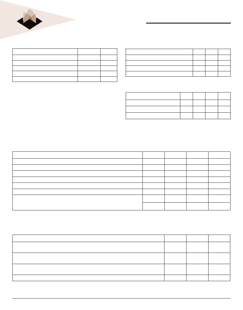
DC ELECTRICAL CHARACTERISTICS AND OPERATING CONDITIONS (NOTES 1, 6)
VCC = +3.3V ±0.3V; -55°C ≤ TA ≤ +125°C
Parameter/Condition
Symbol
Min
Max
Units
Supply Voltage
VCC
3
3.6
V
Input High Voltage: Logic 1; All inputs (21)
VIH
2VCC + 0.3
V
Input Low Voltage: Logic 0; All inputs (21)
VIL
-0.3
0.8
V
Input Leakage Current: Any input 0V VIN VCC (All other pins not under test = 0V)
II
-5
5
μA
Input Leakage Address Current: Any input 0V VIN VCC (All other pins not under test = 0V)
II
-20
20
μA
Output Leakage Current: I/Os are disabled; 0V VOUT VCC
IOZ
-5
5
μA
Output Levels:
Output High Voltage (IOUT = -4mA)
Output Low Voltage (IOUT = 4mA)
VOH
2.4
–
V
VOL
–
0.4
V
ABSOLUTE MAXIMUM RATINGS
Parameter
Unit
Voltage on VCC, VDDQSupply relative to VSS
-1 to 4.6
V
Voltage on NC or I/O pins relative to VSS
-1 to 4.6
V
Operating Temperature TA (Mil)
-55 to +125
°C
Operating Temperature TA (Ind)
-40 to +85
°C
Storage Temperature, Plastic
-55 to +125
°C
NOTE:
Stress greater than those listed under "Absolute Maximum Ratings" may cause
permanent damage to the device. This is a stress rating only and functional
operation of the device at these or any other conditions greater than those
indicated in the operational sections of this specication is not implied. Exposure to
absolute maximum rating conditions for extended periods may affect reliability.
CAPACITANCE (NOTE 2)
Parameter
Symbol Max
Unit
Input Capacitance: CLK
CI1
6
pF
Addresses, BA0-1 Input Capacitance
CA
20
pF
Input Capacitance: All other input-only pins
CI2
6
pF
Input/Output Capacitance: I/Os
CIO
9
pF
IDD SPECIFICATIONS AND CONDITIONS (NOTES 1,6,11,13)
VCC = +3.3V ±0.3V; -55°C ≤ TA ≤ +125°C
Parameter/Condition
Symbol
Max
Units
Operating Current: Active Mode;
Burst = 2; Read or Write; tRC = tRC (min); CAS latency = 3 (3, 18, 19)
ICC1
600
mA
Standby Current: Active Mode; CKE = HIGH; CS# = HIGH;
All banks active after tRCD met; No accesses in progress (3, 12, 19)
ICC3
200
mA
Operating Current: Burst Mode; Continuous burst;
Read or Write; All banks active; CAS latency = 3 (3, 18, 19)
ICC4
600
mA
Self Refresh Current: CKE ≤ 0.2V (Commercial and Industrial temperatures only)
ICC7
8mA
BGA THERMAL RESISTANCE
Description
Symbol Max
Unit
Notes
Junction to Ambient (No Airow)
θJA
17.0
°C/W
1
Junction to Ball
θJB
11.8
°C/W
1
Junction to Case (Top)
θJC
8.5
°C/W
1
NOTE: Refer to BGA Thermal Resistance Correlation application note at
www.whiteedc.com in the application notes section for modeling conditions.
相關(guān)PDF資料 |
PDF描述 |
|---|---|
| WMF2M8-150LM5 | 2M X 8 FLASH 5V PROM, 150 ns, CQCC44 |
| WMF2M8-90LM5A | 2M X 8 FLASH 5V PROM, 90 ns, CQCC44 |
| WS128K32N-15H1IA | 128K X 32 MULTI DEVICE SRAM MODULE, 15 ns, CPGA66 |
| WS128K32L-45G2LM | 128K X 32 MULTI DEVICE SRAM MODULE, 45 ns, CQFP68 |
| W3EG6432S202JD3 | 32M X 64 DDR DRAM MODULE, 0.75 ns, DMA184 |
相關(guān)代理商/技術(shù)參數(shù) |
參數(shù)描述 |
|---|---|
| WEDPN8M64V-133B2M | 制造商:WEDC 制造商全稱:White Electronic Designs Corporation 功能描述:8Mx64 Synchronous DRAM |
| WEDPN8M64V-133BC | 制造商:Microsemi Corporation 功能描述:8M X 64 SDRAM MODULE, 3.3V, 133 MHZ, 219 PBGA 25MM X 25MM, C - Bulk |
| WEDPN8M64VR-XBX | 制造商:未知廠家 制造商全稱:未知廠家 功能描述:Registered SDRAM MCP |
| WEDPN8M64V-XB2X | 制造商:WEDC 制造商全稱:White Electronic Designs Corporation 功能描述:8Mx64 Synchronous DRAM |
| WEDPN8M64V-XBX | 制造商:未知廠家 制造商全稱:未知廠家 功能描述:SDRAM MCP |
發(fā)布緊急采購(gòu),3分鐘左右您將得到回復(fù)。