- 您現(xiàn)在的位置:買賣IC網(wǎng) > PDF目錄371200 > X24256S8I EEPROM PDF資料下載
參數(shù)資料
| 型號: | X24256S8I |
| 元件分類: | EEPROM |
| 英文描述: | EEPROM |
| 中文描述: | EEPROM的 |
| 文件頁數(shù): | 6/18頁 |
| 文件大小: | 144K |
| 代理商: | X24256S8I |

X24256
Characteristics subject to change without notice.
6 of 18
If the master writes more than 64 bytes, then the previ-
ously loaded data is overwritten by the new data, one
byte at a time.
The master terminates the data byte loading by issuing
a stop condition, which causes the device to begin the
nonvolatile write cycle. As with the byte write operation,
all inputs are disabled until completion of the internal
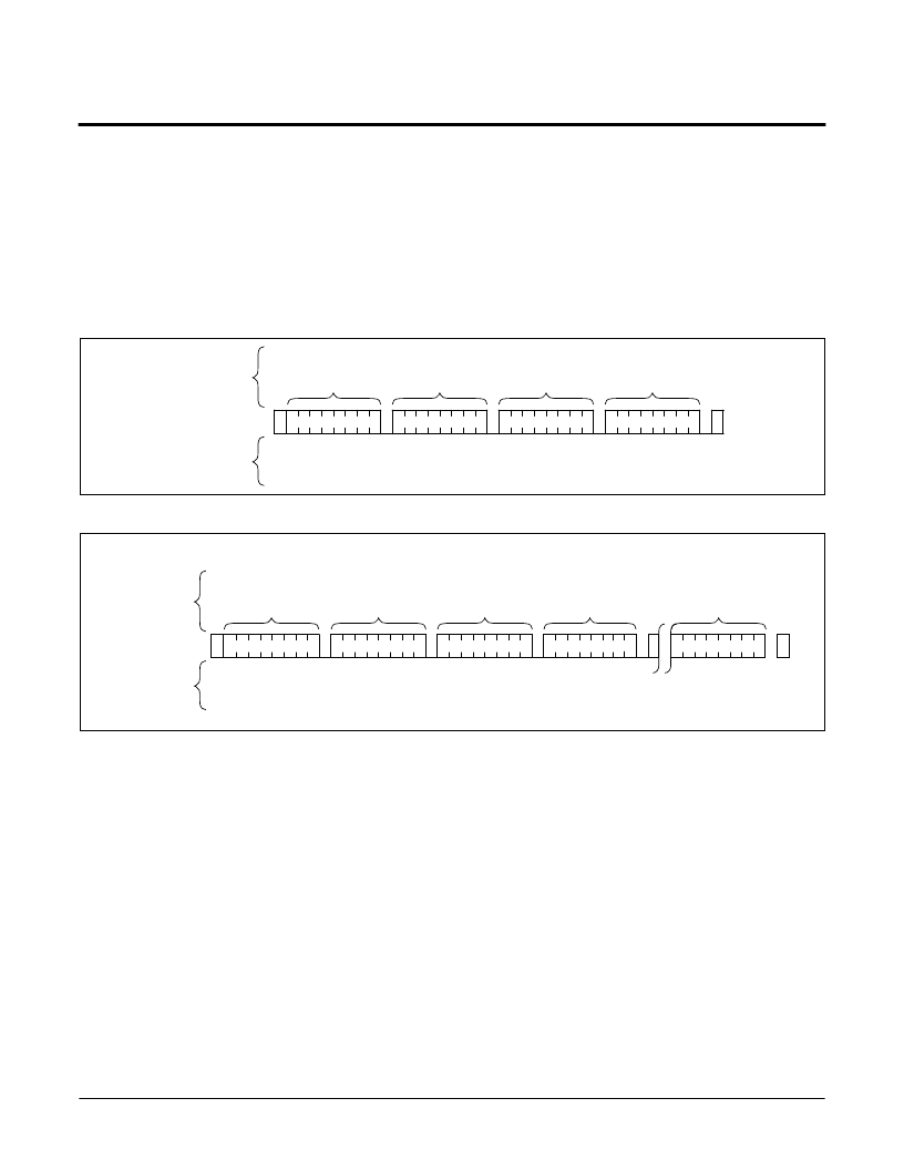
write cycle. Refer to Figure 6 for the address, acknowl-
edge, and data transfer sequence.
Figure 5. Byte Write Sequence
Figure 6. Page Write Sequence
SIGNALS
FROMTHE
MASTER
SDA BUS
SIGNALS
FROMTHE
SLAVE
S
T
A
R
T
S
SLAVE
ADDRESS
S
T
O
P
A
C
K
A
C
K
A
C
K
A
C
K
WORDADDRESS
BYTE 1
DATA
1 0 1 0
WORD ADDRESS
BYTE 0
P
0
0
S
T
A
R
T
SLAVE
ADDRESS
S
T
O
P
P
A
C
K
A
C
K
A
C
K
A
C
K
A
C
K
DATA
(0)
SIGNALS
FROMTHE
MASTER
SDA BUS
SIGNALS
FROMTHE
SLAVE
(n)
WORD ADDRESS
BYTE 1
WORDADDRESS
BYTE 0
0
S
DATA
1 0 1 0
(0
≤
n
≤
64)
0
Stop and Write Modes
Stop conditions that terminate write operations must
be sent by the master after sending at least 1 full data
byte and it’s associated ACK signal. If a stop is issued
in the middle of a data byte, or before 1 full data byte +
ACK is sent, then the device will reset itself without
performing the write. The contents of the array will not
be affected.
Acknowledge Polling
The maximum write cycle time can be significantly
reduced using Acknowledge Polling. To initiate
Acknowledge Polling, the master issues a start condi-
tion followed by the Slave Address Byte for a write or
read operation. If the device is still busy with the inter-
nal write cycle, then no ACK will be returned. If the
device has completed the internal write operation, an
ACK will be returned and the host can then proceed
with the read or write operation. Refer to Figure 7.
Powered by ICminer.com Electronic-Library Service CopyRight 2003
相關(guān)PDF資料 |
PDF描述 |
|---|---|
| X24256S8I-1.8 | EEPROM |
| X24256S8I-2.5 | I2C Serial EEPROM |
| X24256V14 | 55V Single N-Channel HEXFET Power MOSFET in a D-Pak package; A IRFR4105Z with Standard Packaging |
| X24256ZI-1.8 | 30V Single N-Channel HEXFET Power MOSFET in a D2-Pak package; A IRL7833S with Standard Packaging |
| X24256ZI-2.5 | EEPROM |
相關(guān)代理商/技術(shù)參數(shù) |
參數(shù)描述 |
|---|---|
| X24256S8I-1.8 | 制造商:未知廠家 制造商全稱:未知廠家 功能描述:EEPROM |
| X24256S8I-2.5 | 制造商:未知廠家 制造商全稱:未知廠家 功能描述:I2C Serial EEPROM |
| X24256V14 | 制造商:未知廠家 制造商全稱:未知廠家 功能描述:EEPROM |
| X24256V14-1.8 | 制造商:未知廠家 制造商全稱:未知廠家 功能描述:EEPROM |
| X24256V14-2.5 | 制造商:未知廠家 制造商全稱:未知廠家 功能描述:I2C Serial EEPROM |
發(fā)布緊急采購,3分鐘左右您將得到回復。