- 您現(xiàn)在的位置:買賣IC網(wǎng) > PDF目錄371268 > X5645S14-2.7A RTC Module With CPU Supervisor PDF資料下載
參數(shù)資料
| 型號(hào): | X5645S14-2.7A |
| 元件分類: | CPU監(jiān)測(cè) |
| 英文描述: | RTC Module With CPU Supervisor |
| 中文描述: | 時(shí)鐘模塊CPU監(jiān)控 |
| 文件頁(yè)數(shù): | 1/19頁(yè) |
| 文件大小: | 117K |
| 代理商: | X5645S14-2.7A |
當(dāng)前第1頁(yè)第2頁(yè)第3頁(yè)第4頁(yè)第5頁(yè)第6頁(yè)第7頁(yè)第8頁(yè)第9頁(yè)第10頁(yè)第11頁(yè)第12頁(yè)第13頁(yè)第14頁(yè)第15頁(yè)第16頁(yè)第17頁(yè)第18頁(yè)第19頁(yè)

REV 1.1.1 3/5/01
Characteristics subject to change without notice.
1 of 19
www.xicor.com
Replaces X25643/X25645
CPU Supervisor with 64Kbit SPI EEPROM
X5643/X5645
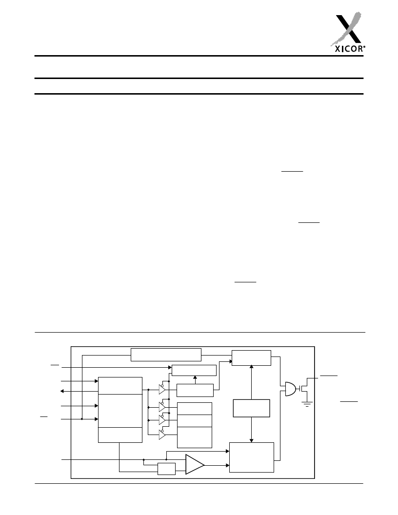
BLOCK DIAGRAM
Watchdog
Timer Reset
Data
Register
Command
Decode &
Control
Logic
SI
SO
SCK
CS/WDI
V
CC
Reset &
Watchdog
Timebase
Power On and
Low Voltage
Generation
V
TRIP
+
-
RESET/RESET
Reset
Status
Register
Protect Logic
16Kbits
16Kbits
32Kbits
E
Watchdog Transition
Detector
WP
V
CC
Threshold
Reset logic
X5643 = RESET
X5645 = RESET
FEATURES
Selectable watchdog timer
Low V
CC
detection and reset assertion
—Five standard reset threshold voltages
—Re-program low V
using special programming sequence
—Reset signal valid to V
Determine watchdog or low voltage reset with a
volatile flag bit
Long battery life with low power consumption
—<50μA max standby current, watchdog on
—<1μA max standby current, watchdog off
—<400μA max active current during read
64Kbits of EEPROM
Built-in inadvertent write protection
—Power-up/power-down protection circuitry
—Protect 0, 1/4, 1/2 or all of EEPROM array with
Block Lock
protection
—In circuit programmable ROM mode
2MHz SPI interface modes (0,0 & 1,1)
Minimize EEPROM programming time
—32-byte page write mode
—Self-timed write cycle
—5ms write cycle time (typical)
2.7V to 5.5V and 4.5V to 5.5V power supply
operation
Available packages
—8-lead PDIP, 14-lead SOIC
CC
reset threshold voltage
CC
= 1V
DESCRIPTION
These devices combine four popular functions, Power-
on Reset Control, Watchdog Timer, Supply Voltage
Supervision, and Block Lock Protect Serial EEPROM
Memory in one package. This combination lowers sys-
tem cost, reduces board space requirements, and
increases reliability.
Applying power to the device activates the power on
reset circuit which holds RESET/RESET active for a
period of time. This allows the power supply and oscilla-
tor to stabilize before the processor can execute code.
The Watchdog Timer provides an independent protection
mechanism for microcontrollers. When the microcon-
troller fails to restart a timer within a selectable time out
interval, the device activates the RESET/RESET signal.
The user selects the interval from three preset values.
Once selected, the interval does not change, even after
cycling the power.
The device’s low V
user’s system from low voltage conditions, resetting
the system when V
CC
falls below the minimum V
trip point. RESET/RESET is asserted until V
to proper operating level and stabilizes. Five industry
standard V
TRIP
thresholds are available, however,
Xicor’s unique circuits allow the threshold to be repro-
grammed to meet custom requirements or to fine-tune
the threshold for applications requiring higher precision.
CC
detection circuitry protects the
CC
CC
returns
相關(guān)PDF資料 |
PDF描述 |
|---|---|
| X5645S14-4.5A | RTC Module With CPU Supervisor |
| X5645S14I | RTC Module With CPU Supervisor |
| X5645S14I-4.5A | RTC Module With CPU Supervisor |
| X5645X14I-4.5A | Analog IC |
| X5645P | RTC Module With CPU Supervisor |
相關(guān)代理商/技術(shù)參數(shù) |
參數(shù)描述 |
|---|---|
| X5645S14-4.5A | 制造商:XICOR 制造商全稱:Xicor Inc. 功能描述:CPU Supervisor with 64Kbit SPI EEPROM |
| X5645S14I | 制造商:XICOR 制造商全稱:Xicor Inc. 功能描述:CPU Supervisor with 64Kbit SPI EEPROM |
| X5645S14I-2.7 | 制造商:Rochester Electronics LLC 功能描述:- Bulk |
| X5645S14I-4.5A | 制造商:XICOR 制造商全稱:Xicor Inc. 功能描述:CPU Supervisor with 64Kbit SPI EEPROM |
| X5645S8-1.8 | 制造商:未知廠家 制造商全稱:未知廠家 功能描述:SPI Serial EEPROM with Supervisory Features |
發(fā)布緊急采購(gòu),3分鐘左右您將得到回復(fù)。