- 您現(xiàn)在的位置:買賣IC網(wǎng) > PDF目錄371269 > X76F041A PASS TM SecureFlash PDF資料下載
參數(shù)資料
| 型號: | X76F041A |
| 英文描述: | PASS TM SecureFlash |
| 中文描述: | 密碼商標SecureFlash |
| 文件頁數(shù): | 16/21頁 |
| 文件大?。?/td> | 107K |
| 代理商: | X76F041A |

X76F041
16
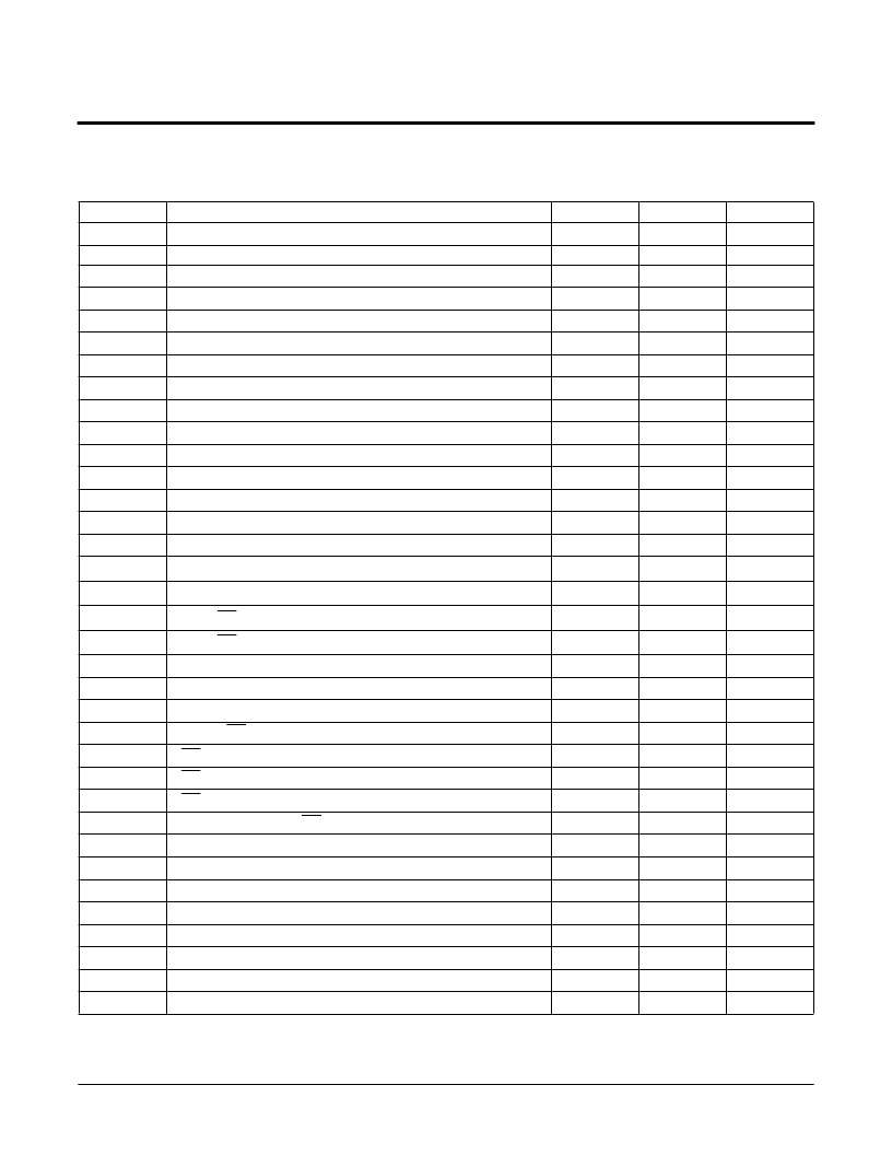
A.C. CHARACTERISTICS
(Over recommended operating conditions, unless otherwise specified)
Read & Write Cycle Limits
7002 FRM T10
NOTES:
(4) This parameter is periodically sampled and not 100% tested.
Symbol
f
SCL
TI
t
DV
t
LOW
t
HIGH
t
STAS1
t
STAS2
t
STAH1
t
STAH2
t
STPS1
t
STPS2
t
STPH1
t
STPH2
t
HD:DAT
t
SU:DAT
t
RSCL
(4)
t
FSCL
(4)
t
R
(4)
t
F
(4)
t
DH
t
HZ1
t
LZ
t
VCCS
t
SU:CS
t
HD:CS
t
HZ2
t
SU:SCL
t
RST
t
SU:RST
f
SCL:RST
t
LOW:RST
t
HIGH:RST
t
PD
t
NOL
t
WC
Parameter
Min.
Max.
1
20
450
Units
MHz
ns
ns
ns
ns
ns
ns
ns
ns
ns
ns
ns
ns
ns
ns
SCL Clock Frequency
Noise Suppression Time Constant at SCL & SDA Inputs
SCL HIGH to SDA Data Valid
Clock LOW Period
Clock HIGH Period
Start Condition Setup Time to Rising Edge of SCL
Start Condition Setup Time to Falling Edge of SCL
Start Condition Hold Time to Rising Edge of SCL
Start Condition Hold Time to Falling Edge of SCL
Stop Condition Setup Time to Rising Edge of SCL
Stop Condition Setup Time to Falling Edge of SCL
Stop Condition Hold Time to Rising Edge of SCL
Stop Condition Hold Time to Falling Edge of SCL
Data in Hold Time
Data in Setup Time
500
500
150
150
50
50
150
150
50
50
10
150
SCL Rise Time
90
ns
SCL Fall Time
90
ns
SDA, CS, RST Rise Time
90
ns
SDA, CS, RST Fall Time
90
ns
Data Out Hold Time
SCL LOW to High Impedance
SCL HIGH to Output Active
V
CC
to CS Setup Time
CS Setup Time
CS Hold Time
CS Deselect Time
SCL Setup Time to CS LOW after Power Up
RST HIGH Time
RST Setup Time
SCL Frequency During Response to Reset
SCL LOW Time During Response to Reset
SCL HIGH Time During Response to Reset
SCL LOW to SDA Valid During Response to Reset
RST to SCL Non-Overlap
Nonvolatile Write Cycle
0
ns
ns
ns
ms
ns
ns
ns
ns
ns
ns
MHz
ns
ns
ns
ns
ms
150
0
5
200
100
150
200
1500
500
1
500
500
450
500
10
相關(guān)PDF資料 |
PDF描述 |
|---|---|
| X76F041A-3 | PASS TM SecureFlash |
| X76F041AE | PASS TM SecureFlash |
| X76F041H | PASS TM SecureFlash |
| X76F041H-3 | PASS TM SecureFlash |
| X76F041HE | PASS TM SecureFlash |
相關(guān)代理商/技術(shù)參數(shù) |
參數(shù)描述 |
|---|---|
| X76F041A-3 | 制造商:XICOR 制造商全稱:Xicor Inc. 功能描述:PASS TM SecureFlash |
| X76F041AE | 制造商:XICOR 制造商全稱:Xicor Inc. 功能描述:PASS TM SecureFlash |
| X76F041AE-3 | 制造商:XICOR 制造商全稱:Xicor Inc. 功能描述:PASS TM SecureFlash |
| X76F041H | 制造商:XICOR 制造商全稱:Xicor Inc. 功能描述:PASS TM SecureFlash |
| X76F041H-3 | 制造商:XICOR 制造商全稱:Xicor Inc. 功能描述:PASS TM SecureFlash |
發(fā)布緊急采購,3分鐘左右您將得到回復(fù)。