- 您現(xiàn)在的位置:買賣IC網(wǎng) > PDF目錄371269 > X76F041H-3 PASS TM SecureFlash PDF資料下載
參數(shù)資料
| 型號(hào): | X76F041H-3 |
| 英文描述: | PASS TM SecureFlash |
| 中文描述: | 密碼商標(biāo)SecureFlash |
| 文件頁(yè)數(shù): | 5/21頁(yè) |
| 文件大小: | 107K |
| 代理商: | X76F041H-3 |
第1頁(yè)第2頁(yè)第3頁(yè)第4頁(yè)當(dāng)前第5頁(yè)第6頁(yè)第7頁(yè)第8頁(yè)第9頁(yè)第10頁(yè)第11頁(yè)第12頁(yè)第13頁(yè)第14頁(yè)第15頁(yè)第16頁(yè)第17頁(yè)第18頁(yè)第19頁(yè)第20頁(yè)第21頁(yè)

X76F041
5
The retry register must have a higher value than the retry
counter for correct device operation. If the retry counter
value is larger than the retry register and the retry
counter is enabled, the device will wrap around allowing
up to an additional 255 incorrect access attempts.
If the Retry counter enable bit is a “0”, then the retry
counter is disabled.
Retry Register/Counter
Both the retry register and retry counter are accessible in
the configuration mode and may be programmed with a
value of 0 to 255.
The difference between the retry register and the retry
counter is the number of access attempts allowed, there-
fore the retry counter must be programmed to a smaller
value than the retry register to prevent wrap around.
DEVICE PROTOCOL
The X76F041 supports a bidirectional bus oriented pro-
tocol. The protocol defines any device that sends data
onto the bus as a transmitter, and the receiving device as
the receiver. The device controlling the transfer is a mas-
ter and the device being controlled is the slave. The mas-
ter will always initiate data transfers, and provide the
clock for both transmit and receive operations. Therefore,
the X76F041 will be considered a slave in all applica-
tions.
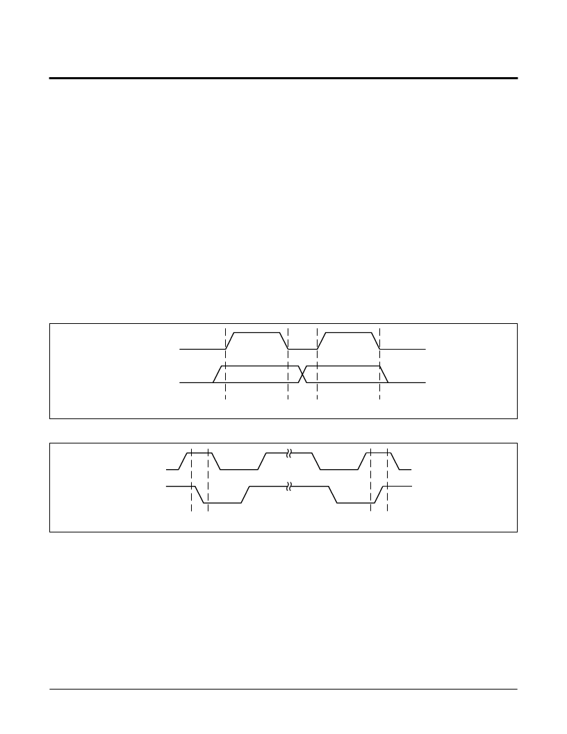
Start Condition
All commands except for response to reset are preceded
by the start condition, which is a HIGH to LOW transition
of SDA when SCL is HIGH. The X76F041 continuously
monitors the SDA and SCL lines for the start condition
and will not respond to any command until this condition
has been met.
Figure 4. Data Validity During Write
Figure 5. Definition of Start and Stop
NOTE:
The part requires the SCL input to be LOW during non-active periods of operation. In other words, the SCL will need to be LOW prior to
any START condition and LOW after a STOP condition. This is also reflected in the timing diagram.
SCL
SDA
DATA STABLE
DATA
CHANGE
7002 ILL F07
SCL
SDA
START BIT
STOP BIT
7002 ILL F08
相關(guān)PDF資料 |
PDF描述 |
|---|---|
| X76F041HE | PASS TM SecureFlash |
| X76F041P | PASS TM SecureFlash |
| X76F041P-3 | PASS TM SecureFlash |
| X76F041PE | PASS TM SecureFlash |
| X76F041W | PASS TM SecureFlash |
相關(guān)代理商/技術(shù)參數(shù) |
參數(shù)描述 |
|---|---|
| X76F041HE | 制造商:XICOR 制造商全稱:Xicor Inc. 功能描述:PASS TM SecureFlash |
| X76F041HE-3 | 制造商:XICOR 制造商全稱:Xicor Inc. 功能描述:PASS TM SecureFlash |
| X76F041P | 制造商:XICOR 制造商全稱:Xicor Inc. 功能描述:PASS TM SecureFlash |
| X76F041P-3 | 制造商:XICOR 制造商全稱:Xicor Inc. 功能描述:PASS TM SecureFlash |
| X76F041PE | 制造商:XICOR 制造商全稱:Xicor Inc. 功能描述:PASS TM SecureFlash |
發(fā)布緊急采購(gòu),3分鐘左右您將得到回復(fù)。