- 您現(xiàn)在的位置:買(mǎi)賣(mài)IC網(wǎng) > PDF目錄371341 > XC612N2533ML Analog IC PDF資料下載
參數(shù)資料
| 型號(hào): | XC612N2533ML |
| 英文描述: | Analog IC |
| 中文描述: | 模擬IC |
| 文件頁(yè)數(shù): | 1/1頁(yè) |
| 文件大小: | 87K |
| 代理商: | XC612N2533ML |

2. Voltage Detectors
_________________________________________________________________________________
●
22
XC612 Series
2 Channel Voltage Detectors
General Description
Features
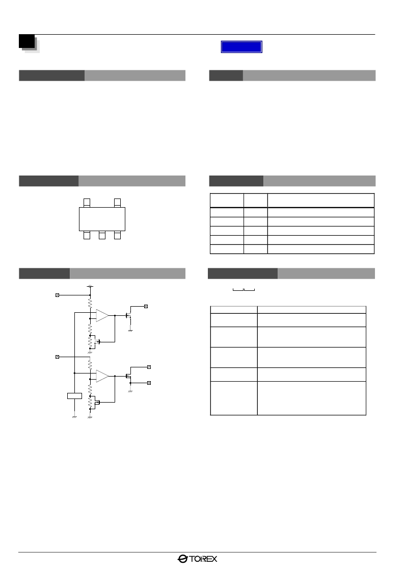
The XC612 series consist of 2 voltage detectors in 1 mini-
molded, SOT-25 package.
The series provides accuracy and low power consumption
through CMOS processing and laser trimming and consists of
a highly accurate voltage reference source, 2 comparators,
hysteresis and output driver circuits.
The input (V
IN1
) for voltage detector 1 (V
D1
) dually functions as
the power supply pin for both detector 1 (V
D1
) and detector 2
(V
D2
).
Highly Accurate:
Set-up voltage accuracy ± 2% (± 1% semi-custom)
Low Power Consumption:
TYP 2.0
μ
A ( V
IN1
=V
IN2
=2.0V, quiescent state)
Detect Voltage:
1.5V to 5.0V programmable in 0.1V steps
Detector's voltages can be set-up independently
Operating Voltage Range:
1.5V to 10.0V
Temp.Characteristics:
± 100ppm/
°
C
Output Configuration:
N-ch open drain
Small Package:
SOT-25 (150mW) mini-mold
* CMOS Output is under development
Pin Configuration
Pin Assignment
1
2
3
SOT-25
(TOP VIEW)
4
5
V
DET1
V
DET2
V
IN1
V
IN2
V
SS
PIN
NUMBER
1
2
3
4
5
PIN
NAME
V
DET1
V
IN1
V
SS
V
IN2
V
DET2
FUNCTION
Voltage Detector 1 Output
Voltage Detector 1 Input, Power Supply
Ground
Voltage detector 2 Input
Voltage Detector 2 Output
Block Diagram
Ordering Information
V
SS
V
IN1
V
IN2
V
DET1
V
DET2
Vref
+
-
+
-
XC612
×××××××
↑
↑
↑
↑↑
a
b
DESIGNATOR
c d e
DESCRIPTION
a
Output Configuration
N = N-ch open drain
Detect Voltage (V
DET1
)
25 = 2.5V
38 = 3.8V
Detect Voltage (V
DET2
)
33 = 3.3V
50 = 5.0V
Package Type
M = SOT-25
Device Orientation
R = Embossed Tape
( Orientation of device : right )
L = Embossed Tape
( Orientation of device : left )
b
c
d
e
DETAILS
相關(guān)PDF資料 |
PDF描述 |
|---|---|
| XC612N2533MR | Analog IC |
| XC612N2550ML | Analog IC |
| XC612N2550MR | Analog IC |
| XC612N3833ML | Analog IC |
| XC612N3833MR | Analog IC |
相關(guān)代理商/技術(shù)參數(shù) |
參數(shù)描述 |
|---|---|
| XC612N4528MRN | 制造商:Torex Semiconductor LTD 功能描述: |
| XC612N5028MRN | 制造商:Torex Semiconductor LTD 功能描述: |
| XC6192AA05ER-G | 功能描述:POWER SAVING PUSH BUTTON LOAD SW 制造商:torex semiconductor ltd 系列:* 零件狀態(tài):在售 標(biāo)準(zhǔn)包裝:1 |
| XC6192BANNER-G | 功能描述:POWER SAVING PUSH BUTTON LOAD SW 制造商:torex semiconductor ltd 系列:* 零件狀態(tài):在售 標(biāo)準(zhǔn)包裝:1 |
| XC61AC2702PR | 制造商:Torex Semiconductor LTD 功能描述:ANALOG IC |
發(fā)布緊急采購(gòu),3分鐘左右您將得到回復(fù)。