- 您現(xiàn)在的位置:買(mǎi)賣(mài)IC網(wǎng) > PDF目錄376465 > XSD314 (CALOGIC LLC) High-Speed Analog N-Channel DMOS FETs Improved On -Resistance PDF資料下載
參數(shù)資料
| 型號(hào): | XSD314 |
| 廠商: | CALOGIC LLC |
| 元件分類(lèi): | 小信號(hào)晶體管 |
| 英文描述: | High-Speed Analog N-Channel DMOS FETs Improved On -Resistance |
| 中文描述: | 50 mA, 20 V, N-CHANNEL, Si, SMALL SIGNAL, MOSFET |
| 封裝: | DIE |
| 文件頁(yè)數(shù): | 1/3頁(yè) |
| 文件大?。?/td> | 35K |
| 代理商: | XSD314 |

Hgh-SpeedAnalog
N-Channel DMOS FETs
ImprovedOn-Resistance
SD310 /SD312 /SD314
FEATURES
High Input to Output Isolation . . . . . . . . . . . . . . . . 120dB
Low On Resistance . . . . . . . . . . . . . . . . . 15 Ohms @ 15V
Low Feedthrough and Feedback Transients
Low Capacitance:
—
Input (Gate) . . . . . . . . . . . . . . . . . . . . . . . . . . 2.4pF typ.
—
Output . . . . . . . . . . . . . . . . . . . . . . . . . . . . . . 1.3pF typ.
—
Feedback. . . . . . . . . . . . . . . . . . . . . . . . . . . . 0.3pF typ.
No Protection Diode from Gate to Substrate for very
high impedance applications
Maximum Gate Voltage. . . . . . . . . . . . . . . . . . . . . . .
±
40V
APPLICATIONS
Analog Switch Driver
Analog Switches
High-Speed Digital Switches
Multiplexers
A to D Converters
D to A Converters
Choppers
Sample & Hold
DESCRIPTION
The Calogic SD310 is a 30V analog switch driver without a
built-in protection diode from gate to substrate for use with
SD312 and SD314 DMOS analog switches.
The SD312 is a high performance, high-speed, high-voltage,
and low resistance analog switch capable of switching
±
5V
signals. The maximum threshold of 2V permits simple direct
TTL an CMOS driving for small applications.
The SD314 is DMOS analog switch capable of switching
±
10V analog signals with all other parameters identical to
those of SD312.
All three devices are manufactured with an implanted
high-speed, high-voltage, and low resistance double-diffused
MOS (DMOS) process. SD310, SD312 and SD314 devices
also have no built-in protection diode to enhance performance
in high impedance circuits. The devices are available in
4-lead hermetic TO-72 package and in die form for hybrid
applications. Custom devices based on SD310, SD312 and
SD314 can also be ordered.
ORDERING INFORMATION
Part
SD310DE
SD312DE
SD314DE
XSD310
XSD312
XSD314
Package
Hermetic TO-72 Package
Hermetic TO-72 Package
Hermetic TO-72 Package
Sorted Chips in Carriers
Sorted Chips in Carriers
Sorted Chips in Carriers
Temperature Range
-55
o
C to +125
o
C
-55
o
C to +125
o
C
-55
o
C to +125
o
C
-55
o
C to +125
o
C
-55
o
C to +125
o
C
-55
o
C to +125
o
C
C ORPORATION
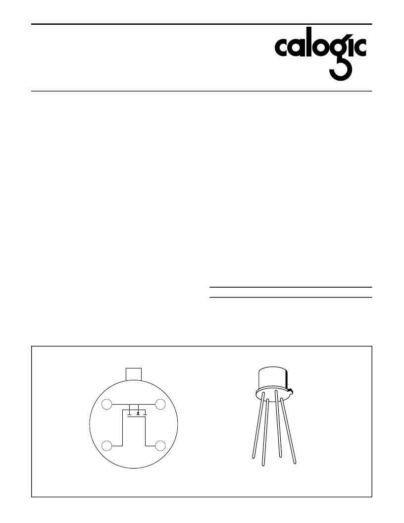
SCHEMATIC DIAGRAM (Top View)
SOURCE
BODY
AND
CASE
GATE
DRAIN
Body is internally connected to the case
1
2
3
4
CD10-2
TO-72
G
D
C
S
相關(guān)PDF資料 |
PDF描述 |
|---|---|
| XSD400 | High-Speed Analog N-Channel/Enhancement-Mode DMOS FETS |
| XSD402 | High-Speed Analog N-Channel/Enhancement-Mode DMOS FETS |
| XSD403 | High Speed DMOS N-Channel Switch |
| XSD404 | High Speed DMOS N-Channel Switch |
| XSD5000 | High-Speed DMOS Quad FET Analog Switch Arrays |
相關(guān)代理商/技術(shù)參數(shù) |
參數(shù)描述 |
|---|---|
| XSD400 | 制造商:CALOGIC 制造商全稱(chēng):CALOGIC 功能描述:High-Speed Analog N-Channel/Enhancement-Mode DMOS FETS |
| XSD402 | 制造商:CALOGIC 制造商全稱(chēng):CALOGIC 功能描述:High-Speed Analog N-Channel/Enhancement-Mode DMOS FETS |
| XSD403 | 制造商:CALOGIC 制造商全稱(chēng):CALOGIC 功能描述:High Speed DMOS N-Channel Switch |
| XSD404 | 制造商:CALOGIC 制造商全稱(chēng):CALOGIC 功能描述:High Speed DMOS N-Channel Switch |
| XSD411 | 制造商:CALOGIC 制造商全稱(chēng):CALOGIC 功能描述:N-Channel Enhancement Mode Dual DMOS FET |
發(fā)布緊急采購(gòu),3分鐘左右您將得到回復(fù)。