- 您現(xiàn)在的位置:買賣IC網(wǎng) > PDF目錄372951 > XTR103BU 4-20mA Current Transmitter with RTD EXCITATION AND LINEARIZATION PDF資料下載
參數(shù)資料
| 型號(hào): | XTR103BU |
| 英文描述: | 4-20mA Current Transmitter with RTD EXCITATION AND LINEARIZATION |
| 中文描述: | 4 - 20mA電流變送器的RTD激勵(lì)和線性化 |
| 文件頁(yè)數(shù): | 7/10頁(yè) |
| 文件大?。?/td> | 222K |
| 代理商: | XTR103BU |

XTR103
7
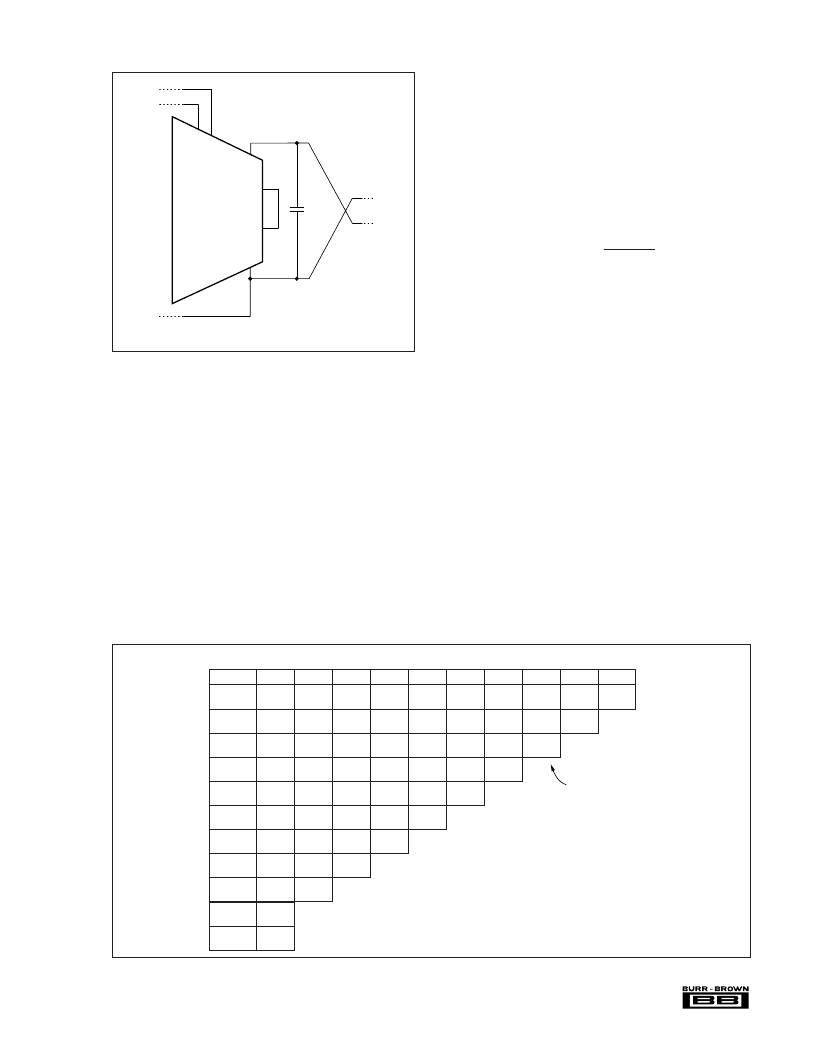
FIGURE 2. Operation Without External Transistor.
TABLE I. R
Z
, R
G
, and R
LIN
Resistor Values for Pt100 RTD.
T
MIN
–200
°
C
100
°
C
18/90
653
60/84
1105
100/81
1287
138/78
1211
175/76
1137
212/73
1066
247/71
996
280/68
930
313/66
865
345/64
803
375/61
743
200
°
C
18/185
838
60/173
1229
100/167 100/260 100/361 100/469 100/588 100/718 100/860
1258
1229
1201
1173
138/162 138/252 138/349 138/453 138/567 138/691
1183
1155
1127
1100
175/157 175/244 175/337 175/437 175/546
1110
1083
1056
1030
212/152 212/235 212/325 212/422
1039
1013
987
962
247/146 247/227 247/313
971
946
921
280/141 280/219
905
881
313/136
841
300
°
C
18/286
996
60/270
1251
400
°
C
18/396
1087
60/374
1249
500
°
C
18/515
1131
60/487
1231
600
°
C
18/645
1152
60/610
1207
700
°
C
18/788
1159
60/746
1181
800
°
C
18/946
1158
60/895
1155
900
°
C
18/1120 18/1317
1154
60/1061
1128
1000
°
C
1140
–100
°
C
0
°
C
1145
1117
1089
100
°
C
1073
1046
200
°
C
1003
300
°
C
400
°
C
500
°
C
600
°
C
700
°
C
800
°
C
MEASUREMENT TEMPERATURE SPAN
T (
°
C)
R
Z
/R
G
R
LIN
11
14
XTR103
0.01μF
E
E
INT
I
O
V+
For operation without external
transistor, connect pin 11 to
pin 14. See text for discussion
of performance.
10
7
(Values are in
.)
NOTE: Values shown are for a Pt100 RTD.
Double (x2) all values for Pt200.
LOOP POWER SUPPLY
The voltage applied to the XTR103, V+, is measured with
respect to the I
O
connection, pin 7. V+ can range from 9V
to
40V. The loop supply voltage, V
PS
, will differ from the
voltage applied to the XTR103 according to the voltage drop
on the current sensing resistor, R
L
(plus any other voltage
drop in the line).
If a low loop supply voltage is used, R
L
must be made a
relatively low value to assure that V+ remains 9V or greater
for the maximum loop current of 20mA. It may, in fact, be
prudent to design for V+ equal or greater than 9V with loop
currents up to 34mA to allow for out-of-range input condi-
tions. The typical performance curve “Loop Resistance vs
Loop Power Supply” shows the allowable sense resistor
values for full-scale 20mA.
The low operating voltage (9V) of the XTR103 allows
operation directly from personal computer power supplies
(12V
±
5%). When used with the RCV420 Current Loop
Receiver
(Figure 8), load resistor voltage drop is limited to
1.5V.
LINEARIZATION
On-chip linearization circuitry creates a signal-dependent
variation in the two matching current sources. Both current
sources are varied equally according to the following equa-
tion:
I
R1
= I
R2
= 0.8 +
(I
R
in mA, V
IN
in volts, R
LIN
in ohms)
(maximum I
R
= 1.0mA)
This varying excitation provides a 2nd-order term to the
transfer function (including the RTD) which can correct the
RTD’s nonlinearity. The correction is controlled by resistor
R
LIN
which is chosen according to the desired temperature
measurement range. Table I provides the R
G
, R
Z
and R
LIN
resistor values for a Pt100 RTD.
If no linearity correction is desired, do not connect a resistor
to the R
LIN
pins (R
LIN
=
∞
). This will cause the excitation
current sources to remain a constant 0.8mA.
ADJUSTING INITIAL ERRORS
Most applications will require adjustment of initial errors.
Offset errors can be corrected by adjustment of the zero
resistor, R
Z
.
Figure 3 shows another way to adjust zero errors using the
output current adjustment pins of the XTR103. This provides
a minimum of
±
300
μ
A (typically
±
500
μ
A) adjustment around
the initial low-scale output current. This is an output current
adjustment which is independent of the input stage gain set
R
LIN
500 V
IN
相關(guān)PDF資料 |
PDF描述 |
|---|---|
| XTR104 | A/D Converter (A-D) IC; Resolution (Bits):20; Sample Rate:100SPS; Input Channels Per ADC:4; Input Channel Type:Differential; Data Interface:Serial; Package/Case:24-SOIC; Leaded Process Compatible:No; No. of Bits:20 RoHS Compliant: Yes |
| XTR104AP | 4-20mA Current Transmitter with BRIDGE EXCITATION AND LINEARIZATION |
| XTR104AU | A/D Converter (A-D) IC; Resolution (Bits):16; Sample Rate:100SPS; Input Channels Per ADC:1; Input Channel Type:Differential; Data Interface:Serial; Package/Case:20-DIP; DNL +/-:0.5LSB; Leaded Process Compatible:No; No. of Bits:16 RoHS Compliant: No |
| XTR104BP | 4-20mA Current Transmitter with BRIDGE EXCITATION AND LINEARIZATION |
| XTR104BU | A/D Converter (A-D) IC; Resolution (Bits):16; Sample Rate:100SPS; Input Channels Per ADC:1; Input Channel Type:Differential; Data Interface:Serial; Package/Case:20-SOIC; DNL +/-:0.5LSB; Leaded Process Compatible:No; No. of Bits:16 RoHS Compliant: No |
相關(guān)代理商/技術(shù)參數(shù) |
參數(shù)描述 |
|---|---|
| XTR104 | 制造商:BB 制造商全稱:BB 功能描述:4-20mA Current Transmitter with BRIDGE EXCITATION AND LINEARIZATION |
| XTR104AP | 制造商:BB 制造商全稱:BB 功能描述:4-20mA Current Transmitter with BRIDGE EXCITATION AND LINEARIZATION |
| XTR104AU | 制造商:Rochester Electronics LLC 功能描述:4-20 MA XMITTER - Bulk |
| XTR104BP | 制造商:Texas Instruments 功能描述:IC 4-20 MA I-TRANSMITTER 16-DIP |
| XTR104BU | 制造商:Texas Instruments 功能描述: |
發(fā)布緊急采購(gòu),3分鐘左右您將得到回復(fù)。