- 您現(xiàn)在的位置:買賣IC網(wǎng) > PDF目錄372951 > XTR104 A/D Converter (A-D) IC; Resolution (Bits):20; Sample Rate:100SPS; Input Channels Per ADC:4; Input Channel Type:Differential; Data Interface:Serial; Package/Case:24-SOIC; Leaded Process Compatible:No; No. of Bits:20 RoHS Compliant: Yes PDF資料下載
參數(shù)資料
| 型號: | XTR104 |
| 英文描述: | A/D Converter (A-D) IC; Resolution (Bits):20; Sample Rate:100SPS; Input Channels Per ADC:4; Input Channel Type:Differential; Data Interface:Serial; Package/Case:24-SOIC; Leaded Process Compatible:No; No. of Bits:20 RoHS Compliant: Yes |
| 中文描述: | 4 - 20mA電流變送器的電橋的激勵和線性化 |
| 文件頁數(shù): | 8/11頁 |
| 文件大小: | 165K |
| 代理商: | XTR104 |
8
XTR104
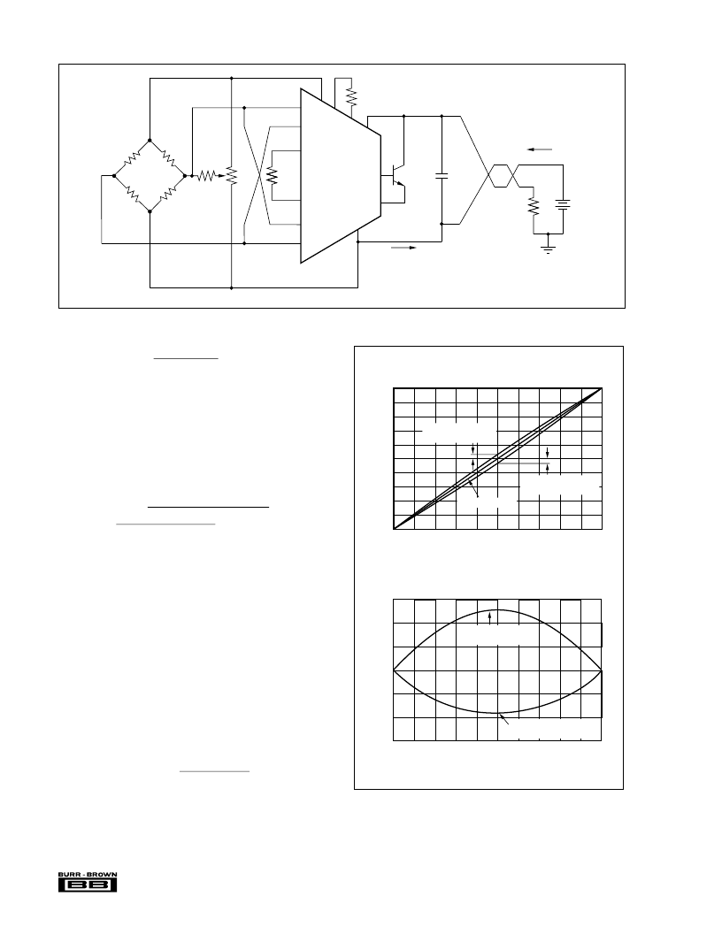
FIGURE 3. Bridge Sensor, V
LIN
Connected for Negative Nonlinearity.
XTR104
R
G
–
+
R
L
–
V
PS
–
+
11
0.01μF
+
13
7
4
6
5
1
(1)
12
10
2
R
B
3
R
LIN
8
9
V
+
LIN
R
G
V
–
LIN
V
+
IN
R
G
V
–
IN
I
O
E
B
V+
R
LIN
Bridge Sensor
R
2
R
1
V
R
I
O
= 4-20mA
4-20mA
NOTE: (1) V
inputs connected for negative nonlinearity (B < 0).
Pins 3 and 4 must be reversed for B > 0 (see Figure 1).
(1)
Use R
LIN
= 632
. Because the calculation yields a negative
result, connect V
+LIN
to V
–IN
and V
–LIN
to V
+IN
.
Gain is affected by the varying the excitation voltage. For
each 1% of corrected nonlinearity, the gain must be altered
by 4%. As a result, equation 2 will not provide an accurate
R
G
when nonlinearity correction is used. The following
equation calculates the required value for R
G
to compensate
for this effect.
(6)
B must again be a signed number in this calculation—
positive for positive bowing nonlinearity, and negative for a
negative-bowing nonlinearity.
R
G
= 23.32
for the example above.
A more accurate value for R
LIN
can be determined by first
measuring the actual gain constant of the linearization in-
puts, K
LIN
(see equation 4). Measure the change in the
reference voltage,
V
R
, in response to a measured voltage
change at the linearization inputs,
V
LIN
. Make this mea-
surement with a known, temporary test value for R
LIN
. These
measurements can be made during operation of the circuit
by providing stimulus to the bridge sensor, or by temporarily
unbalancing the bridge with a fixed resistor in parallel with
one of the bridge resistors. Calculate the actual K
LIN
:
Where:
V
LIN
is the change in voltage at V
LIN
.
V
R
is the measured change in reference voltage, V
R
.
R
TEST
is a temporary fixed value of R
LIN
(in
).
R
LIN
≈
24000 0. 01
0. 2 (
1. 9)
=
632
R
G
=
(1
+
0.04 B) V
FS
2500
1
1
K
LIN
=
V
R
R
TEST
V
LIN
(7)
FIGURE 4. Parabolic Nonlinearity.
BRIDGE TRANSDUCER TRANSFER FUNCTION
WITH PARABOLIC NONLINEARITY
0
10
9
8
7
6
5
4
3
2
1
0
Normalized Stimulus
0.1
0.2
0.3
0.4
0.5
0.6
0.7
0.8
0.9
1
B
Positive Nonlinearity
B = +2.5%
B = –1.9%
Negative Nonlinearity
Linear Response
NONLINEARITY vs STIMULUS
0
3
2
1
0
–1
–2
–3
Normalized Stimulus
0.1
0.2
0.3
0.4
0.5
0.6
0.7
0.8
0.9
1
N
Negative Nonlinearity
B = –1.9%
Positive Nonlinearity
B = +2.5%
相關(guān)PDF資料 |
PDF描述 |
|---|---|
| XTR104AP | 4-20mA Current Transmitter with BRIDGE EXCITATION AND LINEARIZATION |
| XTR104AU | A/D Converter (A-D) IC; Resolution (Bits):16; Sample Rate:100SPS; Input Channels Per ADC:1; Input Channel Type:Differential; Data Interface:Serial; Package/Case:20-DIP; DNL +/-:0.5LSB; Leaded Process Compatible:No; No. of Bits:16 RoHS Compliant: No |
| XTR104BP | 4-20mA Current Transmitter with BRIDGE EXCITATION AND LINEARIZATION |
| XTR104BU | A/D Converter (A-D) IC; Resolution (Bits):16; Sample Rate:100SPS; Input Channels Per ADC:1; Input Channel Type:Differential; Data Interface:Serial; Package/Case:20-SOIC; DNL +/-:0.5LSB; Leaded Process Compatible:No; No. of Bits:16 RoHS Compliant: No |
| XTR106 | A/D Converter (A-D) IC; Resolution (Bits):16; Sample Rate:212SPS; Input Channels Per ADC:1; Input Channel Type:Differential; Data Interface:Serial; Package/Case:8-SOIC; Leaded Process Compatible:No; No. of Bits:18 RoHS Compliant: Yes |
相關(guān)代理商/技術(shù)參數(shù) |
參數(shù)描述 |
|---|---|
| XTR104AP | 制造商:BB 制造商全稱:BB 功能描述:4-20mA Current Transmitter with BRIDGE EXCITATION AND LINEARIZATION |
| XTR104AU | 制造商:Rochester Electronics LLC 功能描述:4-20 MA XMITTER - Bulk |
| XTR104BP | 制造商:Texas Instruments 功能描述:IC 4-20 MA I-TRANSMITTER 16-DIP |
| XTR104BU | 制造商:Texas Instruments 功能描述: |
| XTR105 | 制造商:BB 制造商全稱:BB 功能描述:4-20mA CURRENT TRANSMITTER with Sensor Excitation and Linearization |
發(fā)布緊急采購,3分鐘左右您將得到回復(fù)。