- 您現(xiàn)在的位置:買賣IC網(wǎng) > PDF目錄48109 > YS12S10-0G (POWER-ONE INC) DC-DC REG PWR SUPPLY MODULE PDF資料下載
參數(shù)資料
| 型號(hào): | YS12S10-0G |
| 廠商: | POWER-ONE INC |
| 元件分類: | 電源模塊 |
| 英文描述: | DC-DC REG PWR SUPPLY MODULE |
| 封裝: | ROHS COMPLIANT, MODULE-6 |
| 文件頁(yè)數(shù): | 24/27頁(yè) |
| 文件大小: | 332K |
| 代理商: | YS12S10-0G |
第1頁(yè)第2頁(yè)第3頁(yè)第4頁(yè)第5頁(yè)第6頁(yè)第7頁(yè)第8頁(yè)第9頁(yè)第10頁(yè)第11頁(yè)第12頁(yè)第13頁(yè)第14頁(yè)第15頁(yè)第16頁(yè)第17頁(yè)第18頁(yè)第19頁(yè)第20頁(yè)第21頁(yè)第22頁(yè)第23頁(yè)當(dāng)前第24頁(yè)第25頁(yè)第26頁(yè)第27頁(yè)
MCD10206 Rev. 1.0, 24-Jun-10
Page 6 of 27
www.power-one.com
YS12S10 DC-DC Converter Data Sheet
9.6-14 VDC Input; 0.7525-5.5 VDC Programmable @ 10 A
Because the sense lead carries minimal current,
large traces on the end-user board are not required.
However, sense trace should be located close to a
ground plane to minimize system noise and ensure
the optimum performance.
When utilizing the remote sense feature, care must
be taken not to exceed the maximum allowable
output power capability of the converter which is
equal to the product of the nominal output voltage
and the allowable output current for the given
conditions.
When using remote sense, the output voltage at the
converter can be increased up to 0.5 V above the
nominal rating in order to maintain the required
voltage across the load. Therefore, the designer
must, if necessary, decrease the maximum current
(originally obtained from the derating curves) by the
same percentage to ensure the converter’s actual
output power remains at or below the maximum
allowable output power.
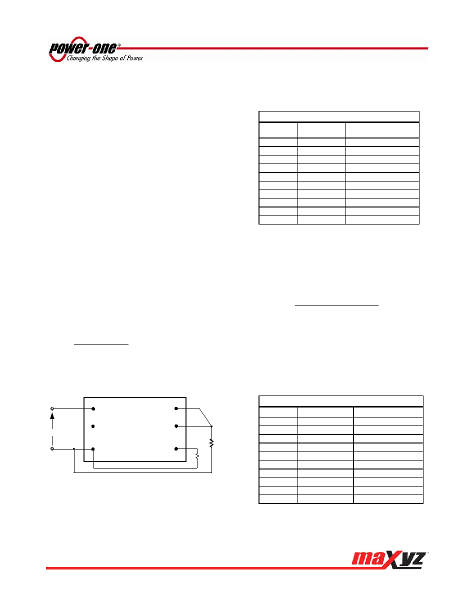
Output Voltage Programming (Pin 3)
The output voltage can be programmed from
0.7525 to 5.5 V by connecting an external resistor
between TRIM pin (Pin 3) and GND pin (Pin 5); see
Fig. C. Note that when trim resistor is not connected,
output voltage of the converter is 0.7525 V.
A trim resistor, RTRIM, for a desired output voltage
can be calculated using the following equation:
1
0.7525)
-
(V
5
.
10
R
REQ
-
O
RIM
T
[k]
where,
TRIM
R
Required value of trim resistor [k]
REQ
O
V
Desired (trimmed) output voltage [V]
Rload
Vin
R T-INCR
Converter
Vin
GND
ON/OFF
SENSE
(Top View)
TRIM
Vout
Y-Series
Fig. C: Configuration for programming output voltage.
Note that the tolerance of a trim resistor directly
affects
the
output
voltage
tolerance.
It
is
recommended to use standard 1% or 0.5% resistors;
for tighter tolerance, two resistors in parallel are
recommended rather than one standard value from
Table 1.
The ground pin of the trim resistor should be
connected directly to the converter GND pin (Pin 5)
with no voltage drop in between. Table 1 provides
the trim resistor values for popular output voltages.
Table 1: Trim Resistor Value
V0-REG [V]
RTRIM [k]
The Closest
Standard Value [k]
0.7525
open
1.0
41.42
41.2
1.2
22.46
22.6
1.5
13.05
13.0
1.8
9.02
9.09
2.0
7.42
7.50
2.5
5.01
4.99
3.3
3.12
3.09
5.0
1.47
5.5
1.21
The output voltage can also be programmed by
external voltage source. To make trimming less
sensitive, a series external resistor REXT is
recommended between TRIM pin and programming
voltage source. Control Voltage can be calculated by
the formula:
15
0.7525)
-
)(V
R
1
(
7
.
0
V
REQ
-
O
EXT
CTRL
[V]
where
CTRL
V
Control voltage [V]
EXT
R
External resistor between TRIM pin and
voltage source; the k value can be chosen
depending on the required output voltage range.
Control voltages with
EXT
R
0 and
EXT
R
15 k are
shown in Table 2.
Table 2: Control Voltage [VDC]
V0-REG [V]
VCTRL (REXT = 0)
VCTRL(REXT = 15 k)
0.7525
0.700
1.0
0.684
0.436
1.2
0.670
0.223
1.5
0.650
-0.097
1.8
0.630
-0.417
2.0
0.617
-0.631
2.5
0.584
-1.164
3.3
0.530
-2.017
5.0
0.417
-3.831
5.5
0.384
-4.364
相關(guān)PDF資料 |
PDF描述 |
|---|---|
| YS12S10-DG | DC-DC REG PWR SUPPLY MODULE |
| YS12S10-D | DC-DC REG PWR SUPPLY MODULE |
| YS12S16-0G | 1-OUTPUT DC-DC REG PWR SUPPLY MODULE |
| YS12S16-0 | 1-OUTPUT DC-DC REG PWR SUPPLY MODULE |
| YS12S16-DG | 1-OUTPUT DC-DC REG PWR SUPPLY MODULE |
相關(guān)代理商/技術(shù)參數(shù) |
參數(shù)描述 |
|---|---|
| YS12S10-D | 功能描述:DC/DC轉(zhuǎn)換器 RoHS:否 制造商:Murata 產(chǎn)品: 輸出功率: 輸入電壓范圍:3.6 V to 5.5 V 輸入電壓(標(biāo)稱): 輸出端數(shù)量:1 輸出電壓(通道 1):3.3 V 輸出電流(通道 1):600 mA 輸出電壓(通道 2): 輸出電流(通道 2): 安裝風(fēng)格:SMD/SMT 封裝 / 箱體尺寸: |
| YS12S10-DG | 功能描述:DC/DC轉(zhuǎn)換器 RoHS:否 制造商:Murata 產(chǎn)品: 輸出功率: 輸入電壓范圍:3.6 V to 5.5 V 輸入電壓(標(biāo)稱): 輸出端數(shù)量:1 輸出電壓(通道 1):3.3 V 輸出電流(通道 1):600 mA 輸出電壓(通道 2): 輸出電流(通道 2): 安裝風(fēng)格:SMD/SMT 封裝 / 箱體尺寸: |
| YS12S16 | 制造商:Power-One 功能描述:DC-DC Converter, 9.6-14 VDC In., 0.7525-5.5 VDC Programmable @ 16 A, RoHS |
| YS12S16-0 | 功能描述:DC/DC轉(zhuǎn)換器 RoHS:否 制造商:Murata 產(chǎn)品: 輸出功率: 輸入電壓范圍:3.6 V to 5.5 V 輸入電壓(標(biāo)稱): 輸出端數(shù)量:1 輸出電壓(通道 1):3.3 V 輸出電流(通道 1):600 mA 輸出電壓(通道 2): 輸出電流(通道 2): 安裝風(fēng)格:SMD/SMT 封裝 / 箱體尺寸: |
| YS12S16-0G | 功能描述:DC/DC轉(zhuǎn)換器 0.7525-5.5Vout 16A 9.6-14Vin RoHS:否 制造商:Murata 產(chǎn)品: 輸出功率: 輸入電壓范圍:3.6 V to 5.5 V 輸入電壓(標(biāo)稱): 輸出端數(shù)量:1 輸出電壓(通道 1):3.3 V 輸出電流(通道 1):600 mA 輸出電壓(通道 2): 輸出電流(通道 2): 安裝風(fēng)格:SMD/SMT 封裝 / 箱體尺寸: |
發(fā)布緊急采購(gòu),3分鐘左右您將得到回復(fù)。