- 您現(xiàn)在的位置:買賣IC網(wǎng) > PDF目錄373758 > Z30-16-5-75 (MINI-CIRCUITS) AC-DC Converter, 5Watt, Input VAC: 90~260, Output VDC: 15/-15, Max Output Current(A): ??0.16, Package: Encapsulated, Isolation(VDC): 3000, Operating Temp.: -25??C to +70??C/40??C to +70??C, Low Ripple & Noise, High Efficiency up to 76%,Single & Dual Ouputs, Regulated, Switching PDF資料下載
參數(shù)資料
| 型號: | Z30-16-5-75 |
| 廠商: | MINI-CIRCUITS |
| 元件分類: | 衰減器 |
| 英文描述: | AC-DC Converter, 5Watt, Input VAC: 90~260, Output VDC: 15/-15, Max Output Current(A): ??0.16, Package: Encapsulated, Isolation(VDC): 3000, Operating Temp.: -25??C to +70??C/40??C to +70??C, Low Ripple & Noise, High Efficiency up to 76%,Single & Dual Ouputs, Regulated, Switching |
| 中文描述: | 5 MHz - 1500 MHz RF/MICROWAVE DIRECTIONAL COUPLER, 2 dB INSERTION LOSS-MAX |
| 封裝: | CASE K18 |
| 文件頁數(shù): | 1/1頁 |
| 文件大小: | 76K |
| 代理商: | Z30-16-5-75 |
Electrical Specifications (T
AMB
= -55°C to 100°C)
Maximum Ratings
Operating Temperature
Storage Temperature
Coaxial Connections
PORT
INPUT
OUTPUT
COUPLED
Features
very flat coupling
very broad, multi-octave
all welded construction
protected by U.S. Patent 6140887 & 6784531
db
1
2
3
-55°C to 100°C
-55°C to 100°C
FREQ.
RANGE
(MHz)
COUPLING
(dB)
f
L
-f
U
5-1000
1000-1500
16.5±0.5
17.7±0.5
±0.5
±0.7
1.1
—
2.0
—
1.1
1.3
1.6
1.9
1.2 1.7
—
22
—
16
—
24
19
16
—
24
—
—
—
1.30
1.30
0.5
0.5
1.0
1.0
—
CASE STYLE: K18
CONNECTORS: BNC
PRICE: $29.95 ea. QTY (1-24)
VSWR
(:1)
Nom.
POWER
INPUT, W
L
Max.
MU
Max.
DIRECTIVITY
(dB)
Typ.
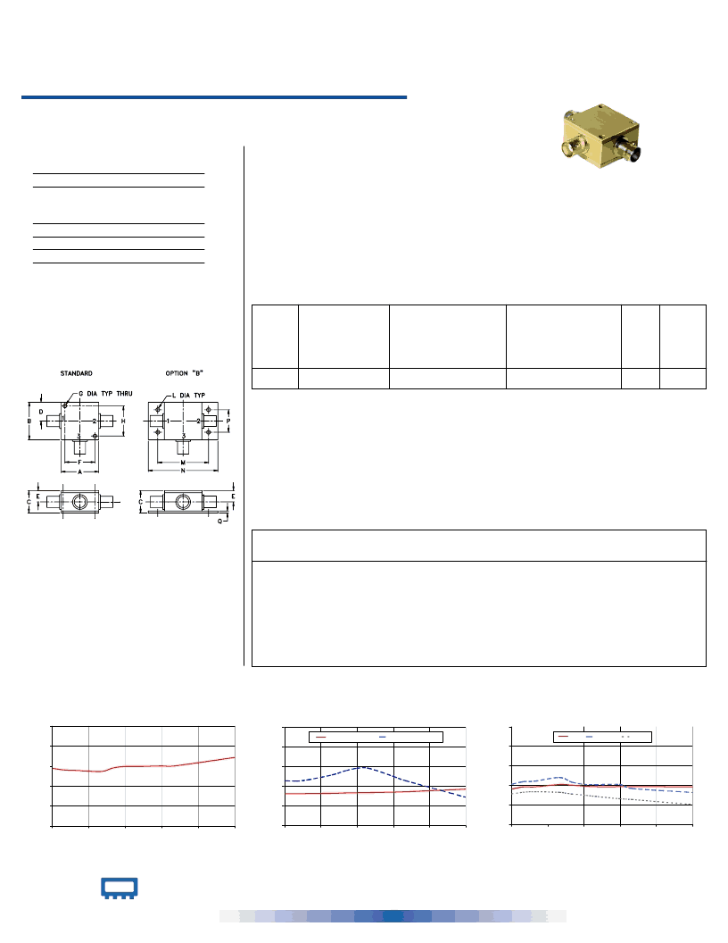
Outline Drawing
Outline Dimensions ( )
inch
mm
Z30-16-5-75
Z30-16-5-75
INSERTION LOSS
0.0
0.4
0.8
1.2
1.6
2.0
0
300
600
900
1200
1500
FREQUENCY (MHz)
I
at RF level of -10 dBm
Z30-16-5-75
RETURN LOSS
0
10
20
30
40
50
0
300
600
900
1200
1500
FREQUENCY (MHz)
R
IN
OUT
CPL
at RF level of -10 dBm
Z30-16-5-75
COUPLING & DIRECTIVITY
at RF level of -10 dBm
0
10
20
30
40
50
0
300
600
900
1200
1500
FREQUENCY (MHz)
C
D
COUPLING
DIRECTIVITY
Typical Performance Data
Frequency
(MHz)
Insertion Loss
(dB)
In-Out
1.15
1.12
1.11
1.09
1.16
1.19
1.19
1.20
1.20
1.37
Coupling
(dB)
In-Cpl
16.13
16.12
16.15
16.29
16.45
16.57
16.65
16.91
17.08
18.42
Directivity
(dB)
Return Loss
(dB)
Out
20.51
21.83
22.15
23.93
21.60
20.47
20.31
20.36
18.32
16.30
In
Cpl
15.57
16.44
16.67
16.35
15.53
14.96
14.28
13.11
12.70
10.13
NEW!
L
Typ. Max.
M
Typ. Max.
U
Typ. Max.
L
Typ. Min.
M
Typ. Min.
U
Typ. Min.
A
B
C
D
E
F
G
H
1.25
31.75
1.25
31.75
.75
.63
.38
9.65
1.00
25.40
.125
3.18
1.00
25.40
19.05
16.00
J
--
--
K
--
--
L
M
N
P
Q
wt
.125
3.18
1.688
42.88
2.18
55.37
2.18
55.37
.07 grams
1.78
70.0
5.00
22.69
22.52
23.21
25.72
27.66
28.98
28.99
24.93
22.79
14.32
18.09
19.15
19.20
20.37
20.02
19.57
19.24
19.23
19.29
19.15
100.00
200.00
400.00
500.00
600.00
700.00
900.00
1000.00
1500.00
VHF/UHF
instrumentation
communications receivers & transmitters
cable tv
Applications
Typ.
Flatness
MAINLINE LOSS
1
(dB)
L = low range [f
to 10 f
] M = mid range [10 f
to f
/2] U = upper range [f
U
/2 to f
U
]
1. Mainline loss includes theoretical power loss at coupled port.
75
5 to 1500 MHz
Directional Coupler
INTERNET
http://www.minicircuits.com
P.O. Box 350166, Brooklyn, New York 11235-0003 (718) 934-4500 Fax (718) 332-4661
Distribution Centers
NORTH AMERICA 800-654-7949 417-335-5935 Fax 417-335-5945 E
UROPE 44-1252-832600
Fax 44-1252-837010
Mini-Circuits
ISO 9001 & ISO 14001
Certified
Mini-Circuits
REV. B
M95492
EDR-5761
Z30-16-5-75
RVN/TD/CP
041119
Coaxial
相關(guān)PDF資料 |
PDF描述 |
|---|---|
| Z300 | 24 Characters x 2 Lines, 5x7 Dot Matrix Character and Cursor |
| Z320 | Low Current Operation at 250??A???Low Reverse Leakage,Low Noise Zener Diode(250??A?·¥?????μ?μ?????°????????????μ?μ?????????a?£°???é???o3?o???????) |
| Z330 | Low Current Operation at 250??A???Low Reverse Leakage,Low Noise Zener Diode(250??A?·¥?????μ?μ?????°????????????μ?μ?????????a?£°???é???o3?o???????) |
| Z310 | Low Current Operation at 250??A???Low Reverse Leakage,Low Noise Zener Diode(250??A?·¥?????μ?μ?????°????????????μ?μ?????????a?£°???é???o3?o???????) |
| Z33M581S | Power products international ltd |
相關(guān)代理商/技術(shù)參數(shù) |
參數(shù)描述 |
|---|
發(fā)布緊急采購,3分鐘左右您將得到回復。