- 您現(xiàn)在的位置:買賣IC網(wǎng) > PDF目錄372963 > Z86E3016FSC (ZiLOG, Inc.) Z8 4K OTP Microcontroller PDF資料下載
參數(shù)資料
| 型號: | Z86E3016FSC |
| 廠商: | ZiLOG, Inc. |
| 英文描述: | Z8 4K OTP Microcontroller |
| 中文描述: | Z8 4K的檢察官辦公室單片機 |
| 文件頁數(shù): | 32/66頁 |
| 文件大小: | 453K |
| 代理商: | Z86E3016FSC |
第1頁第2頁第3頁第4頁第5頁第6頁第7頁第8頁第9頁第10頁第11頁第12頁第13頁第14頁第15頁第16頁第17頁第18頁第19頁第20頁第21頁第22頁第23頁第24頁第25頁第26頁第27頁第28頁第29頁第30頁第31頁當前第32頁第33頁第34頁第35頁第36頁第37頁第38頁第39頁第40頁第41頁第42頁第43頁第44頁第45頁第46頁第47頁第48頁第49頁第50頁第51頁第52頁第53頁第54頁第55頁第56頁第57頁第58頁第59頁第60頁第61頁第62頁第63頁第64頁第65頁第66頁
Z86E30/E31/E40
Z8 4K OTP Microcontroller
Zilog
32
P R E L I M I N A R Y
DS97Z8X0500
FUNCTIONAL DESCRIPTION
The MCU incorporates the following special functions to
enhance the standard Z8 architecture to provide the user
with increased design flexibility.
RESET.
The device is reset in one of three ways:
1.
Power-On Reset
2.
Watch-Dog Timer
3.
STOP-Mode Recovery Source
Note:
Having the Auto Power-on Reset circuitry built-in,
the MCU does not need to be connected to an external
power-on reset circuit. The reset time is 5 ms (typical). The
MCU does not re-initialize WDTMR, SMR, P2M, and P3M
registers to their reset values on a STOP-Mode Recovery
operation.
Note:
The device V
CC
must rise up to the operating V
CC
specification before the TPOR expires.
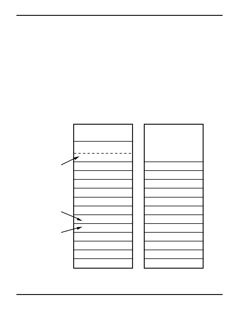
Program Memory.
The MCU can address up to 4 KB of
Internal Program Memory (Figure 22). The first 12 bytes of
program memory are reserved for the interrupt vectors.
These locations contain six 16-bit vectors that correspond
to the six available interrupts. For EPROM mode, byte 12
(000CH) to address 4095 (0FFFH) consists of program-
mable EPROM. After reset, the program counter points at
the address 000CH, which is the starting address of the
user program.
In ROMless mode, the Z86E40 can address up to 64 KB
of External Program Memory. The ROM/ROMless option
is only available on the 44-pin devices.
Figure 22. Program Memory Map
(ROMless Z86E40 Only)
12
11
10
9
8
7
6
5
4
3
2
1
0
External
ROM and RAM
Location of
First Byte of
Instruction
Executed
After RESET
Interrupt
Vector
(Lower Byte)
Interrupt
Vector
(Upper Byte)
IRQ5
IRQ4
IRQ4
IRQ3
IRQ3
IRQ2
IRQ2
IRQ1
IRQ1
IRQ0
IRQ0
IRQ5
On-Chip One Time PROM
External
ROM and RAM
IRQ5
IRQ4
IRQ4
IRQ3
IRQ3
IRQ2
IRQ2
IRQ1
IRQ1
IRQ0
IRQ0
IRQ5
65535
EPROM
ROMless
4096
4095
相關PDF資料 |
PDF描述 |
|---|---|
| Z86E3116FSC | Z8 4K OTP Microcontroller |
| Z86E3016FSE | Z8 4K OTP Microcontroller |
| Z86E4016FSE | Z8 4K OTP Microcontroller |
| Z86E3116FSE | Z8 4K OTP Microcontroller |
| Z86E3016KSC | Z8 4K OTP Microcontroller |
相關代理商/技術參數(shù) |
參數(shù)描述 |
|---|---|
| Z86E3016FSE | 制造商:ZILOG 制造商全稱:ZILOG 功能描述:Z8 4K OTP Microcontroller |
| Z86E3016KEC | 制造商:ZILOG 制造商全稱:ZILOG 功能描述:Z8 4K OTP Microcontroller |
| Z86E3016KEE | 制造商:ZILOG 制造商全稱:ZILOG 功能描述:Z8 4K OTP Microcontroller |
| Z86E3016KSC | 制造商:ZILOG 制造商全稱:ZILOG 功能描述:Z8 4K OTP Microcontroller |
| Z86E3016KSE | 制造商:ZILOG 制造商全稱:ZILOG 功能描述:Z8 4K OTP Microcontroller |
發(fā)布緊急采購,3分鐘左右您將得到回復。