- 您現(xiàn)在的位置:買賣IC網(wǎng) > PDF目錄371369 > 214Z (Intersil Corporation) Li-ion/Li-Polymer Battery Charger Accepting Two Power Sources PDF資料下載
參數(shù)資料
| 型號(hào): | 214Z |
| 廠商: | Intersil Corporation |
| 英文描述: | Li-ion/Li-Polymer Battery Charger Accepting Two Power Sources |
| 中文描述: | 鋰聚合物電池充電器可供兩個(gè)電源 |
| 文件頁(yè)數(shù): | 9/11頁(yè) |
| 文件大小: | 197K |
| 代理商: | 214Z |

9
FN9271.1
November 30, 2006
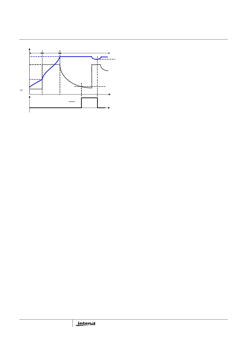
FIGURE 11. TYPICAL CHARGE CYCLE
Figure 11 shows the typical charge profile including the end-
of-charge event.
Power Presence Indication
When either the USB or the cradle input voltage is above the
POR threshold, the PPR pin internal open-drain MOSFET
turns on indicating the presence of input power.
Power-Good Conditions
Even if there is a power present, the charger will not deliver
any current to the output if the power-good conditions are
not met. The following two conditions together define the
power-good voltage range:
1. VCDRL or VUSB > VPOR
2. VCDRL or VUSB - VBAT > VOS
where VPOR is the power on reset threshold, VOS is the
offset voltage for the input and output voltage comparator, All
these thresholds have hysteresis, as given in the Electrical
Specification table. The charger will not charge the battery if
the input voltage does not meet the power-good conditions.
Thermal Foldback (Thermaguard)
The thermal foldback function reduces the charge current
when the internal temperature reaches the thermal foldback
threshold, which is typically 125°C. This protects the charger
from excessive thermal stress at high input voltages.
Input Bypass Capacitors
Due to the inductance of the power leads of the wall adapter
or USB source, the input capacitor type must be properly
selected to prevent high voltage transient during a hot-plug
event. A tantalum capacitors is a good choice for its high
ESR, providing damping to the voltage transient. Multi-layer
ceramic capacitors, however, have a very low ESR and
hence when chosen as input capacitors, a 1-
Ω
series
resistor must be used, as shown in the Typical Applications
Section, to provide adequate damping.
State Diagram
The state diagram for the charger functions is shown in
Figure 12. The diagram starts with the Power-Off state.
When at least one input voltage rises above the POR
threshold, the charge resets it self. If both input voltages are
above the POR threshold, the charger selects the CRDL
input as the power source. Then if the EN pin is at a logic
HIGH voltage, the charger stays in disabled state. If the EN
pin goes LOW, the fast charge starts. Any time the EN pin
turns HIGH, the charger returns to the disabled state. When
the EOC condition is reached, the CHG will turn to logic
HIGH to indicate a charge complete status but the charge
will continue. The EOC condition is then latched until one of
the four re-charge conditions is encountered, as shown in
Figure 11.
IREF
TRICKLE
CC
CV
IREF
18
100
IMIN
4.2V
TIME
2.6V
CHARGE
CURRENT
CHARGE
VOLTAGE
3.9V
CHG
INDICATION
ISL9214
相關(guān)PDF資料 |
PDF描述 |
|---|---|
| 215.2 | Fuse |
| 215.25 | Fuse |
| 215.4 | Fuse |
| 215.5 | Fuse |
| 215.63 | Programmable 8 bit Silicon Delay Line |
相關(guān)代理商/技術(shù)參數(shù) |
參數(shù)描述 |
|---|---|
| 215 | 功能描述:RF RELAY OUTPUT MODULE 8 CH RoHS:是 類別:RF/IF 和 RFID >> RF配件 系列:- 標(biāo)準(zhǔn)包裝:1 系列:* |
| 215 100 55 | 制造商:Werma 功能描述:Bulk |
| 215 100 68 | 制造商:Werma 功能描述: |
| 215 IN STOCK @.95 30 @ | 制造商: 功能描述: 制造商:undefined 功能描述: |
| 215.125P | 制造商:LITTELFUSE 制造商全稱:Littelfuse 功能描述:High breaking capacity |
發(fā)布緊急采購(gòu),3分鐘左右您將得到回復(fù)。