- 您現(xiàn)在的位置:買賣IC網(wǎng) > PDF目錄371417 > 27C010 (Fairchild Semiconductor Corporation) 1,048,576-Bit (128K x 8) High Performance CMOS EPROM PDF資料下載
參數(shù)資料
| 型號: | 27C010 |
| 廠商: | Fairchild Semiconductor Corporation |
| 英文描述: | 1,048,576-Bit (128K x 8) High Performance CMOS EPROM |
| 中文描述: | 1,048,576位(128K的× 8)高性能CMOS存儲器 |
| 文件頁數(shù): | 3/9頁 |
| 文件大?。?/td> | 256K |
| 代理商: | 27C010 |

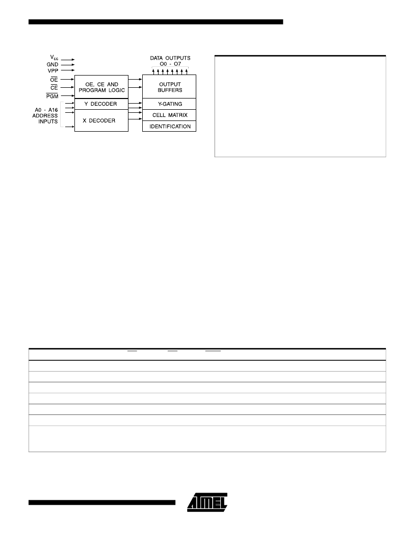
Block Diagram
Temperature Under Bias ................ -55°C to +125°C
Storage Temperature...................... -65°C to +150°C
Voltage on Any Pin with
Respect to Ground.........................-2.0V to +7.0V
(1)
Voltage on A9 with
Respect to Ground ......................-2.0V to +14.0V
(1)
V
PP
Supply Voltage with
Respect to Ground.......................-2.0V to +14.0V
(1)
*NOTICE: Stresses beyond those listed under “Absolute Maxi-
mum Ratings” may cause permanent damage to the device.
This is a stress rating only and functional operation of the
device at these or any other conditions beyond those indi-
cated in the operational sections of this specification is not
implied. Exposure to absolute maximum rating conditions
for extended periods may affect device reliability.
Note:
1. Minimum voltage is -0.6V dc which may undershoot
to -2.0V for pulses of less than 20 ns. Maximum out-
put pin voltage is V
CC
+ 0.75V dc which may over-
shoot to +7.0V for pulses of less than 20 ns.
Absolute Maximum Ratings*
Operating Modes
Mode \ Pin
Read
Output Disable
Standby
Rapid Program
(2)
PGM Verify
PGM Inhibit
CE
V
IL
X
V
IH
V
IL
V
IL
V
IH
OE
V
IL
V
IH
X
V
IH
V
IL
X
PGM
X
(1)
X
X
V
IL
V
IH
X
Ai
Ai
X
X
Ai
Ai
X
V
PP
X
X
X
V
PP
V
PP
V
PP
Outputs
D
OUT
High Z
High Z
D
IN
D
OUT
High Z
Product Identification
(4)
V
IL
V
IL
X
A9 = V
H
(
3
)
A0 = V
IH
or V
IL
A1 - A16 = V
IL
X
Identification
Code
Notes: 1. X can be V
IL
or V
IH
.
2. Refer to Programming characteristics.
3. V
H
= 12.0
±
0.5V.
4. Two identifier bytes may be selected. All Ai inputs
are held low (V
IL
), except A9 which is set to V
H
and A0
which is toggled low (V
IL
) to select the Manufacturer’s Identi-
fication byte and high (V
IH
) to select the Device Code byte.
AT27C010/L
3-155
相關(guān)PDF資料 |
PDF描述 |
|---|---|
| 27C020 | LED 470NM BLUE SMD PLCC4 |
| 27C020 | LED 591NM AMBER SMD PLCC4 |
| 27C024-70 | 1M-BIT [128K x 8/64K x 16] CMOS EPROM |
| 27C1024-10 | 1M-BIT [128K x 8/64K x 16] CMOS EPROM |
| 27C1024-12 | 1M-BIT [128K x 8/64K x 16] CMOS EPROM |
相關(guān)代理商/技術(shù)參數(shù) |
參數(shù)描述 |
|---|---|
| 27C010-120DI | 制造商:Rochester Electronics LLC 功能描述: |
| 27C010-120JC | 制造商:Advanced Micro Devices 功能描述: |
| 27C010-150DC | 制造商: 功能描述: 制造商:undefined 功能描述: |
| 27C01045JI | 制造商: 功能描述: 制造商:undefined 功能描述: |
| 27C010-45JI | 制造商: 功能描述: 制造商:undefined 功能描述: |
發(fā)布緊急采購,3分鐘左右您將得到回復(fù)。