- 您現(xiàn)在的位置:買賣IC網(wǎng) > PDF目錄371440 > 29LV800BE (Fujitsu Limited) 8M (1M x 8/512 K x 16) BIT PDF資料下載
參數(shù)資料
| 型號: | 29LV800BE |
| 廠商: | Fujitsu Limited |
| 英文描述: | 8M (1M x 8/512 K x 16) BIT |
| 中文描述: | 8米(3米x五百一十二分之八畝× 16)位 |
| 文件頁數(shù): | 25/58頁 |
| 文件大小: | 292K |
| 代理商: | 29LV800BE |
第1頁第2頁第3頁第4頁第5頁第6頁第7頁第8頁第9頁第10頁第11頁第12頁第13頁第14頁第15頁第16頁第17頁第18頁第19頁第20頁第21頁第22頁第23頁第24頁當前第25頁第26頁第27頁第28頁第29頁第30頁第31頁第32頁第33頁第34頁第35頁第36頁第37頁第38頁第39頁第40頁第41頁第42頁第43頁第44頁第45頁第46頁第47頁第48頁第49頁第50頁第51頁第52頁第53頁第54頁第55頁第56頁第57頁第58頁

MBM29LV800TE/BE
60/70/90
24
DQ
2
Toggle Bit II
This toggle bit II, along with DQ
6
, can be used to determine whether the devices are in the Embedded Erase
Algorithm or in Erase Suspend.
Successive reads from the erasing sector will cause DQ
2
to toggle during the Embedded Erase Algorithm. If the
devices are in the erase-suspended-read mode, successive reads from the erase-suspended sector will cause
DQ
2
to toggle. When the devices are in the erase-suspended-program mode, successive reads from the byte
address of the non-erase suspended sector will indicate a logic “1” at the DQ
2
bit.
DQ
6
is different from DQ
2
in that DQ
6
toggles only when the standard program or Erase, or Erase Suspend
Program operation is in progress. The behavior of these two status bits, along with that of DQ
7
, is summarized
as follows :
For example, DQ
2
and DQ
6
can be used together to determine if the erase-suspend-read mode is in progress.
(DQ
2
toggles while DQ
6
does not.) See also “Hardware Sequence Flags” and “DQ
2
vs. DQ
6
” in “
I
TIMING
DIAGRAM”.
Furthermore, DQ
2
can also be used to determine which sector is being erased. When device is in the erase
mode, DQ
2
toggles if this bit is read from an erasing sector.
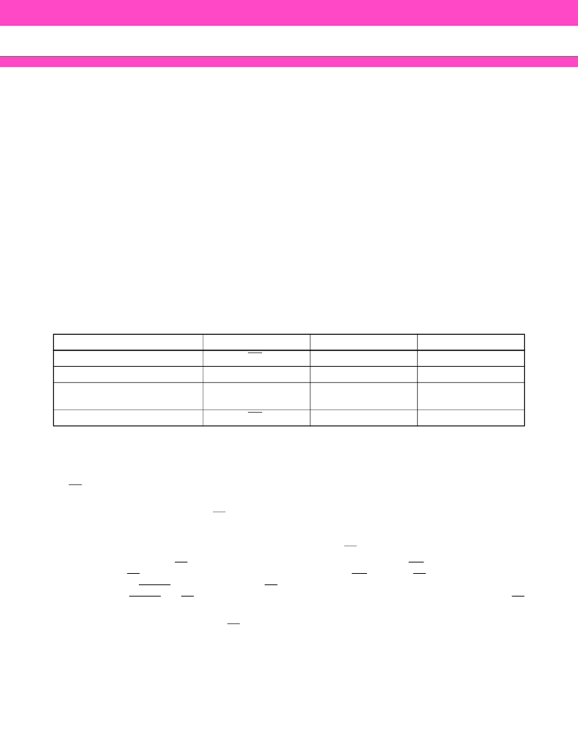
Toggle Bit Status
*1 : Performing successive read operations from any address will cause DQ
6
to toggle.
*2 : Reading the byte address being programmed while in the erase-suspend program mode will indicate logic “1”
at the DQ
2
bit. However, successive reads from the erase-suspended sector will cause DQ
2
to toggle.
RY/BY
Ready/Busy
MBM29LV800TE/BE provide a RY/BY open-drain output pin as a way to indicate to the host system that Em-
bedded Algorithms are either in progress or has been completed. If output is low, devices are busy with either
a program or erase operation. If output is high, devices are ready to accept any read/write or erase operation.
If MBM29LV800TE/BE are placed in an Erase Suspend mode, RY/BY output will be high.
During programming, RY/BY pin is driven low after the rising edge of the fourth WE pulse. During an erase
operation, RY/BY pin is driven low after the rising edge of the sixth WE pulse. RY/BY pin will indicate a busy
condition during RESET pulse. Refer to “RY/BY Timing Diagram during Program/Erase Operation Timing
Diagram” and “RESET, RY/BY Timing Diagram” in “
I
TIMING DIAGRAM” for a detailed timing diagram. RY/BY
pin is pulled high in standby mode.
Since this is an open-drain output, RY/BY pins can be tied together in parallel with a pull-up resistor to V
CC
.
Mode
DQ
7
DQ
6
DQ
2
Program
DQ
7
Toggle
1
Erase
0
Toggle
Toggle
Erase-Suspend Read
(Erase-Suspended Sector) *
1
1
1
Toggle
Erase-Suspend Program
DQ
7
Toggle *
1
1 *
2
相關(guān)PDF資料 |
PDF描述 |
|---|---|
| 29LV800TE | 8M (1M x 8/512 K x 16) BIT |
| 29PL256N | 256/128/128 Mb (16/8/8 M x 16-Bit) CMOS, 3.0 Volt-only Simultaneous Read/Write, Page-Mode Flash Memory |
| 29PS | 25PS, 42PS, 44PS, 45PS and 46PS Series Pressure Switches |
| 29SL800CB-90 | 8M-BIT [1Mx8/512K x16] CMOS SINGLE VOLTAGE 1.8V ONLY FLASH MEMORY |
| 29SL800CT-90 | 8M-BIT [1Mx8/512K x16] CMOS SINGLE VOLTAGE 1.8V ONLY FLASH MEMORY |
相關(guān)代理商/技術(shù)參數(shù) |
參數(shù)描述 |
|---|---|
| 29LV800BT-70 | 制造商:MCNIX 制造商全稱:Macronix International 功能描述:8M-BIT [1Mx8/512K x16] CMOS SINGLE VOLTAGE 3V ONLY FLASH MEMORY |
| 29LV800BT-90 | 制造商:MCNIX 制造商全稱:Macronix International 功能描述:8M-BIT [1Mx8/512K x16] CMOS SINGLE VOLTAGE 3V ONLY FLASH MEMORY |
| 29LV800TE | 制造商:FUJITSU 制造商全稱:Fujitsu Component Limited. 功能描述:8M (1M x 8/512 K x 16) BIT |
| 29M132 | 功能描述:工業(yè)移動感應(yīng)器和位置傳感器 RESISTIVE & OPTICAL RoHS:否 制造商:Honeywell 輸出類型:Analog - Current 電壓額定值:12 VDC to 30 VDC 線性:+/- 0.0011 % 溫度范圍:- 40 C to + 85 C 總電阻: 容差: 類型:Rotary Sensor |
| 29M30050R008BL | 制造商:Micro Plastics Inc 功能描述: |
發(fā)布緊急采購,3分鐘左右您將得到回復。