- 您現(xiàn)在的位置:買賣IC網(wǎng) > PDF目錄68796 > 5962-9089502MCA (TEXAS INSTRUMENTS INC) OP-AMP, 50 uV OFFSET-MAX, 1.9 MHz BAND WIDTH, CDIP14 PDF資料下載
參數(shù)資料
| 型號(hào): | 5962-9089502MCA |
| 廠商: | TEXAS INSTRUMENTS INC |
| 元件分類: | 運(yùn)算放大器 |
| 英文描述: | OP-AMP, 50 uV OFFSET-MAX, 1.9 MHz BAND WIDTH, CDIP14 |
| 封裝: | CERAMIC, DIP-14 |
| 文件頁數(shù): | 32/36頁 |
| 文件大?。?/td> | 916K |
| 代理商: | 5962-9089502MCA |
第1頁第2頁第3頁第4頁第5頁第6頁第7頁第8頁第9頁第10頁第11頁第12頁第13頁第14頁第15頁第16頁第17頁第18頁第19頁第20頁第21頁第22頁第23頁第24頁第25頁第26頁第27頁第28頁第29頁第30頁第31頁當(dāng)前第32頁第33頁第34頁第35頁第36頁

TLC2654, TLC2654A
Advanced LinCMOS
LOW-NOISE CHOPPER-STABILIZED
OPERATIONAL AMPLIFIERS
SLOS020G – NOVEMBER 1988 – REVISED APRIL 2001
5
POST OFFICE BOX 655303
DALLAS, TEXAS 75265
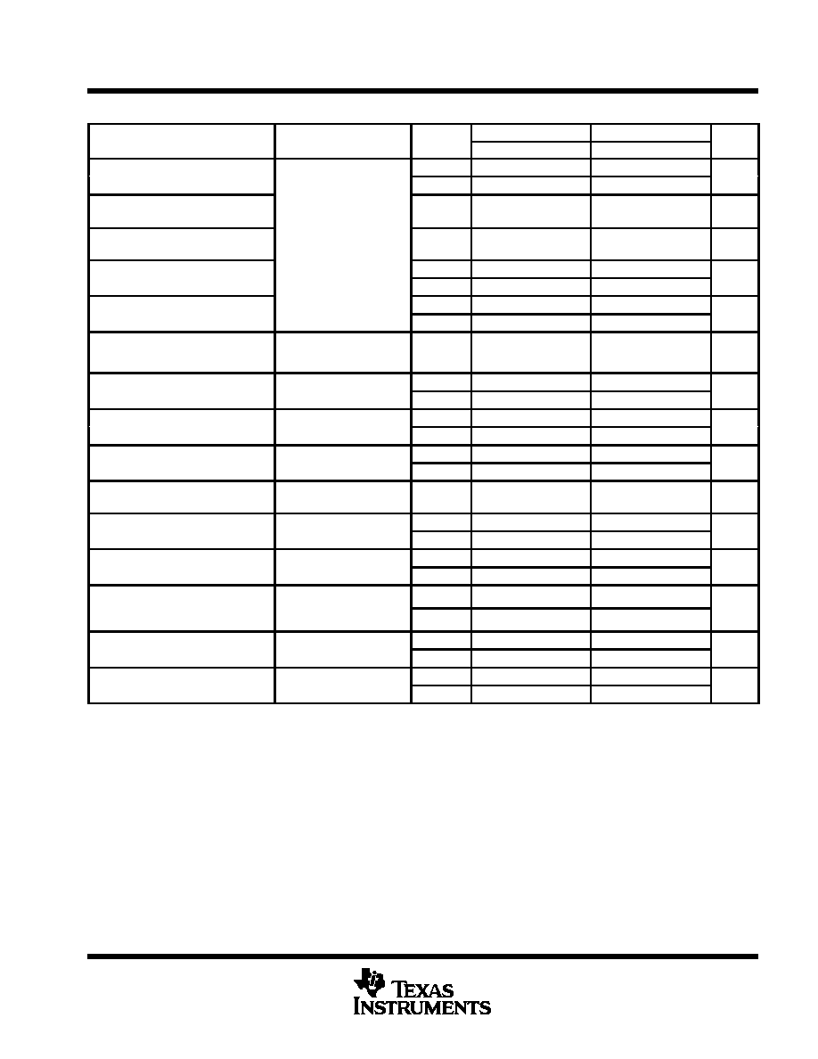
electrical characteristics at specified free-air temperature, VDD± = ±5 V (unless otherwise noted)
PARAMETER
TEST CONDITIONS
TA
TLC2654C
TLC2654AC
UNIT
PARAMETER
TEST CONDITIONS
TA
MIN
TYP
MAX
MIN
TYP
MAX
UNIT
VIO
Input offset voltage
25
°C
5
20
4
10
V
VIO
g
(see Note 4)
Full range
34
24
V
αVIO
Temperature coefficient of
Full range
001
005
001
005
V/°C
αVIO
input offset voltage
Full range
0.01
0.05
0.01
0.05
V/°C
Input offset voltage
long-term drift (see Note 5)
VIC = 0,
RS = 50
25
°C
0.003
0.06
0.003
0.02
V/mo
IIO
Input offset current
25
°C
30
60
30
60
pA
IIO
Input offset current
Full range
150
pA
IIB
Input bias current
25
°C
50
60
50
60
pA
IIB
Input bias current
Full range
150
pA
VICR
Common-mode input
RS =50
Full range
– 5
to
– 5
to
V
VICR
voltage range
RS = 50
Full range
to
2.7
to
2.7
V
VOM
Maximum positive peak
RL =10k
See Note 6
25
°C
4.7
4.8
4.7
4.8
V
VOM +
output voltage swing
RL = 10 k, See Note 6
Full range
4.7
V
VOM
Maximum negative peak
RL =10k
See Note 6
25
°C
– 4.7
– 4.9
– 4.7
– 4.9
V
VOM –
g
output voltage swing
RL = 10 k, See Note 6
Full range
– 4.7
V
AVD
Large-signal differential
VO = ± 4V
RL =10k
25
°C
120
155
135
155
dB
AVD
gg
voltage amplification
VO = ± 4 V,
RL = 10 k
Full range
120
130
dB
Internal chopping
frequency
25
°C
10
kHz
Clamp on state current
RL = 100 k
25
°C
25
A
Clamp on-state current
RL = 100 k
Full range
25
A
Clamp off state current
VO =
4Vto4V
25
°C
100
pA
Clamp off-state current
VO = – 4 V to 4 V
Full range
100
pA
CMRR
Common-mode rejection
VO = 0,
VIC VICRmin
25
°C
105
125
110
125
dB
CMRR
j
ratio
VIC = VICRmin,
RS = 50
Full range
105
110
dB
kSVR
Supply voltage rejection
VDD
± = ±2.3 V to ±8 V,
25
°C
110
125
110
125
dB
kSVR
yg
j
ratio (
VDD±/VIO)
DD
±
,
VO = 0,
RS = 50
Full range
110
dB
IDD
Supply current
VO =0
No load
25
°C
1.5
2.4
1.5
2.4
mA
IDD
Supply current
VO = 0,
No load
Full range
2.5
mA
Full range is 0
°C to 70°C.
NOTES:
4. This parameter is not production tested full range. Thermocouple effects preclude measurement of the actual VIO of these devices
in high-speed automated testing. VIO is measured to a limit determined by the test equipment capability at the temperature extremes.
The test ensures that the stabilization circuitry is performing properly.
5. Typical values are based on the input offset voltage shift observed through 168 hours of operating life test at TA = 150°C extrapolated
to TA = 25° using the Arrhenius equation and assuming an activation energy of 0.96 eV.
6. Output clamp is not connected.
相關(guān)PDF資料 |
PDF描述 |
|---|---|
| 5962-9089502MPA | OP-AMP, 50 uV OFFSET-MAX, 1.9 MHz BAND WIDTH, CDIP8 |
| 5962-9089504QCA | OP-AMP, 40 uV OFFSET-MAX, 1.9 MHz BAND WIDTH, CDIP14 |
| 5962-9089504QPA | OP-AMP, 40 uV OFFSET-MAX, 1.9 MHz BAND WIDTH, CDIP8 |
| 5962-9089502M2A | OP-AMP, 50 uV OFFSET-MAX, 1.9 MHz BAND WIDTH, CQCC20 |
| 5962-9089601M2A | OP-AMP, 105 uV OFFSET-MAX, 13 MHz BAND WIDTH, CQCC20 |
相關(guān)代理商/技術(shù)參數(shù) |
參數(shù)描述 |
|---|---|
| 5962-9089503M2A | 制造商:Texas Instruments 功能描述:SP Amp Chopper Stabilization Single 制造商:Rochester Electronics LLC 功能描述:- Bulk |
| 5962-9089503MPA | 制造商:Texas Instruments 功能描述:SP Amp Chopper Stabilization Single 制造商:Texas Instruments 功能描述:SP Amp Chopper Stabilization Single ±8V/16V 8-Pin CDIP Tube |
| 5962-9089504QPA | 制造商:Texas Instruments 功能描述:SP Amp Chopper Stabilization Single |
| 5962-9089601M2A | 制造商:Texas Instruments 功能描述:OP Amp Single GP 制造商:Texas Instruments 功能描述:OP AMP SGL GP 19V 20LCCC - Rail/Tube |
| 5962-9089601MPA | 制造商:Texas Instruments 功能描述:OP Amp Single GP |
發(fā)布緊急采購,3分鐘左右您將得到回復(fù)。