- 您現(xiàn)在的位置:買賣IC網 > PDF目錄369304 > 74F525SCX (NATIONAL SEMICONDUCTOR CORP) Programmable Counter PDF資料下載
參數(shù)資料
| 型號: | 74F525SCX |
| 廠商: | NATIONAL SEMICONDUCTOR CORP |
| 元件分類: | 通用總線功能 |
| 英文描述: | Programmable Counter |
| 中文描述: | F/FAST SERIES, ASYN POSITIVE EDGE TRIGGERED DOWN DIVIDE BY N COUNTER, PDSO28 |
| 封裝: | 0.300 INCH, PLASTIC, SOIC-28 |
| 文件頁數(shù): | 2/10頁 |
| 文件大?。?/td> | 184K |
| 代理商: | 74F525SCX |

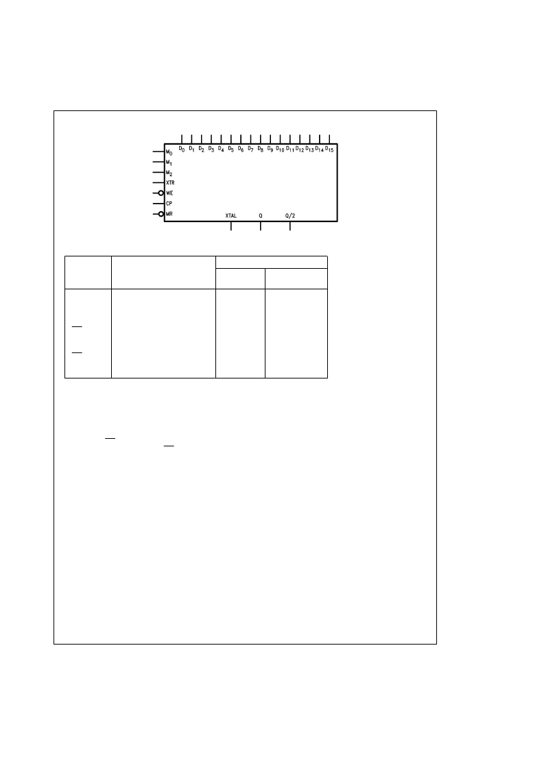
Logic Symbol
TL/F/9547–1
Unit Loading/Fan Out
74F
Pin Names
Description
U.L.
Input I
IH
/I
IL
Output I
OH
/I
OL
HIGH/LOW
Q
Ouput (Primarily indicates when
the counter has reached zero)
Output (Divides Q by 2)
Status Inputs
Master Reset
Clock Pulse
Data Inputs
Write Enable Input
External Trigger Input
Crystal Output
50/33.3
b
1 mA/20 mA
Q/2
M
0
–M
2
MR
CP
D
0
–D
15
WE
XTR
XTAL
50/33.3
1.0/1.0
1.0/1.0
1.0/2.0
1.0/1.0
1.0/1.0
1.0/2.0
1.0/1.0
b
1 mA/20 mA
20
m
A/
b
0.6 mA
20
m
A/
b
0.6 mA
20
m
A/
b
1.2 mA
20
m
A/
b
0.6 mA
20
m
A/
b
0.6 mA
20
m
A/
b
1.2 mA
20
m
A/
b
0.6 mA
Functional Description
The multi-function aspect of the device consists of eight
different modes of operation. An explanation of the opera-
tion of the device in each of the modes follows. However,
there is one operation that is independent of the selected
mode: the loading of data. Data is latched into a set of data
latches when WE is brought from a LOW to a HIGH state.
The latches are transparent when WE is held LOW.
Operation Notes:
1. Device should be reset before operation.
2. The XTR input acts as a select line for the clock.
3. With XTR low, the clock goes into the counter.
4. With XTR high, the clock loads the counter.
5. In mode 4 and 5, during counting, the counter cannot be
reloaded. XTR high freezes the count.
6. Mode 7 is the only auto-reload mode, all other modes
require and XTR pulse to begin.
7. Loading 0 into the latches idles the device.
MODE 0: Interval Timer with Level Output
While XTR is HIGH, the data in the data latches is loaded
into the counter upon the next positive edge of CP. The
negative edge of XTR enables the count-down to begin with
the next positive edge of CP. When the count reaches zero,
Q, normally LOW, is brought HIGH and Q/2 toggles state.
Taking XTR HIGH at any time enables the data in the data
latches to be loaded into the counter on the rising edge of
CP and clears Q. See Figure 1.
MODE 1: Interval Timer with Inverted Level Output
The operation is exactly the same as in Mode 0 except that
Q is normally HIGH and goes LOW when the count reaches
zero. Q/2 toggles on the negative-edge of Q. SeeFigure 1.
MODE 2: Interval Timer with Pulse Output
While XTR is HIGH, the data in the data latches is loaded
into the counter upon the next positive edge of CP. The
negative edge of XTR enables the count-down to begin with
the next positive edge of CP. When the count reaches zero,
Q, normally LOW, is brought HIGH for a single period of CP.
Q/2 toggles state on the positive edge of Q. Taking XTR
HIGH at any time causes the data in the data latches to be
loaded into the counter on the rising edge of CP and clears
Q. See Figure 2.
MODE 3: Interval Timer with Inverted Pulse Output
The operation is exactly the same as in Mode 2 except that
Q is normally HIGH and goes LOW for a single period of CP.
Q/2 toggles on the negative edge of Q. See Figure 2.
2
相關PDF資料 |
PDF描述 |
|---|---|
| 74F525 | Programmable Counter |
| 74F525PCX | Programmable Counter |
| 74F525QCX | Programmable Counter |
| 74F676SPC | 16-Bit Serial/Parallel-In, Serial-Out Shift Register |
| 74F676SC | 16-Bit Serial/Parallel-In, Serial-Out Shift Register |
相關代理商/技術參數(shù) |
參數(shù)描述 |
|---|---|
| 74F5300 | 制造商:PHILIPS 制造商全稱:NXP Semiconductors 功能描述:Fiber optic LED driver |
| 74F5302 | 制造商:PHILIPS 制造商全稱:NXP Semiconductors 功能描述:Fiber optic dual LED/clock driver |
| 74F533 | 制造商:NSC 制造商全稱:National Semiconductor 功能描述:Octal Transparent Latch with TRI-STATE Outputs |
| 74F533_TKH3026B WAF | 制造商:Fairchild Semiconductor Corporation 功能描述: |
| 74F533DC | 制造商:未知廠家 制造商全稱:未知廠家 功能描述:8-Bit D-Type Latch |
發(fā)布緊急采購,3分鐘左右您將得到回復。