- 您現(xiàn)在的位置:買賣IC網(wǎng) > PDF目錄360530 > 7721 7721 Group USER'S MANUALHardware Manual & Device User's Manual 4616K/SEP.26.97 PDF資料下載
參數(shù)資料
| 型號: | 7721 |
| 英文描述: | 7721 Group USER'S MANUALHardware Manual & Device User's Manual 4616K/SEP.26.97 |
| 中文描述: | 7721組用戶MANUALHardware手冊 |
| 文件頁數(shù): | 9/577頁 |
| 文件大?。?/td> | 4616K |
| 代理商: | 7721 |
第1頁第2頁第3頁第4頁第5頁第6頁第7頁第8頁當前第9頁第10頁第11頁第12頁第13頁第14頁第15頁第16頁第17頁第18頁第19頁第20頁第21頁第22頁第23頁第24頁第25頁第26頁第27頁第28頁第29頁第30頁第31頁第32頁第33頁第34頁第35頁第36頁第37頁第38頁第39頁第40頁第41頁第42頁第43頁第44頁第45頁第46頁第47頁第48頁第49頁第50頁第51頁第52頁第53頁第54頁第55頁第56頁第57頁第58頁第59頁第60頁第61頁第62頁第63頁第64頁第65頁第66頁第67頁第68頁第69頁第70頁第71頁第72頁第73頁第74頁第75頁第76頁第77頁第78頁第79頁第80頁第81頁第82頁第83頁第84頁第85頁第86頁第87頁第88頁第89頁第90頁第91頁第92頁第93頁第94頁第95頁第96頁第97頁第98頁第99頁第100頁第101頁第102頁第103頁第104頁第105頁第106頁第107頁第108頁第109頁第110頁第111頁第112頁第113頁第114頁第115頁第116頁第117頁第118頁第119頁第120頁第121頁第122頁第123頁第124頁第125頁第126頁第127頁第128頁第129頁第130頁第131頁第132頁第133頁第134頁第135頁第136頁第137頁第138頁第139頁第140頁第141頁第142頁第143頁第144頁第145頁第146頁第147頁第148頁第149頁第150頁第151頁第152頁第153頁第154頁第155頁第156頁第157頁第158頁第159頁第160頁第161頁第162頁第163頁第164頁第165頁第166頁第167頁第168頁第169頁第170頁第171頁第172頁第173頁第174頁第175頁第176頁第177頁第178頁第179頁第180頁第181頁第182頁第183頁第184頁第185頁第186頁第187頁第188頁第189頁第190頁第191頁第192頁第193頁第194頁第195頁第196頁第197頁第198頁第199頁第200頁第201頁第202頁第203頁第204頁第205頁第206頁第207頁第208頁第209頁第210頁第211頁第212頁第213頁第214頁第215頁第216頁第217頁第218頁第219頁第220頁第221頁第222頁第223頁第224頁第225頁第226頁第227頁第228頁第229頁第230頁第231頁第232頁第233頁第234頁第235頁第236頁第237頁第238頁第239頁第240頁第241頁第242頁第243頁第244頁第245頁第246頁第247頁第248頁第249頁第250頁第251頁第252頁第253頁第254頁第255頁第256頁第257頁第258頁第259頁第260頁第261頁第262頁第263頁第264頁第265頁第266頁第267頁第268頁第269頁第270頁第271頁第272頁第273頁第274頁第275頁第276頁第277頁第278頁第279頁第280頁第281頁第282頁第283頁第284頁第285頁第286頁第287頁第288頁第289頁第290頁第291頁第292頁第293頁第294頁第295頁第296頁第297頁第298頁第299頁第300頁第301頁第302頁第303頁第304頁第305頁第306頁第307頁第308頁第309頁第310頁第311頁第312頁第313頁第314頁第315頁第316頁第317頁第318頁第319頁第320頁第321頁第322頁第323頁第324頁第325頁第326頁第327頁第328頁第329頁第330頁第331頁第332頁第333頁第334頁第335頁第336頁第337頁第338頁第339頁第340頁第341頁第342頁第343頁第344頁第345頁第346頁第347頁第348頁第349頁第350頁第351頁第352頁第353頁第354頁第355頁第356頁第357頁第358頁第359頁第360頁第361頁第362頁第363頁第364頁第365頁第366頁第367頁第368頁第369頁第370頁第371頁第372頁第373頁第374頁第375頁第376頁第377頁第378頁第379頁第380頁第381頁第382頁第383頁第384頁第385頁第386頁第387頁第388頁第389頁第390頁第391頁第392頁第393頁第394頁第395頁第396頁第397頁第398頁第399頁第400頁第401頁第402頁第403頁第404頁第405頁第406頁第407頁第408頁第409頁第410頁第411頁第412頁第413頁第414頁第415頁第416頁第417頁第418頁第419頁第420頁第421頁第422頁第423頁第424頁第425頁第426頁第427頁第428頁第429頁第430頁第431頁第432頁第433頁第434頁第435頁第436頁第437頁第438頁第439頁第440頁第441頁第442頁第443頁第444頁第445頁第446頁第447頁第448頁第449頁第450頁第451頁第452頁第453頁第454頁第455頁第456頁第457頁第458頁第459頁第460頁第461頁第462頁第463頁第464頁第465頁第466頁第467頁第468頁第469頁第470頁第471頁第472頁第473頁第474頁第475頁第476頁第477頁第478頁第479頁第480頁第481頁第482頁第483頁第484頁第485頁第486頁第487頁第488頁第489頁第490頁第491頁第492頁第493頁第494頁第495頁第496頁第497頁第498頁第499頁第500頁第501頁第502頁第503頁第504頁第505頁第506頁第507頁第508頁第509頁第510頁第511頁第512頁第513頁第514頁第515頁第516頁第517頁第518頁第519頁第520頁第521頁第522頁第523頁第524頁第525頁第526頁第527頁第528頁第529頁第530頁第531頁第532頁第533頁第534頁第535頁第536頁第537頁第538頁第539頁第540頁第541頁第542頁第543頁第544頁第545頁第546頁第547頁第548頁第549頁第550頁第551頁第552頁第553頁第554頁第555頁第556頁第557頁第558頁第559頁第560頁第561頁第562頁第563頁第564頁第565頁第566頁第567頁第568頁第569頁第570頁第571頁第572頁第573頁第574頁第575頁第576頁第577頁

7721 Group User’s Manual
ii
Table of contents
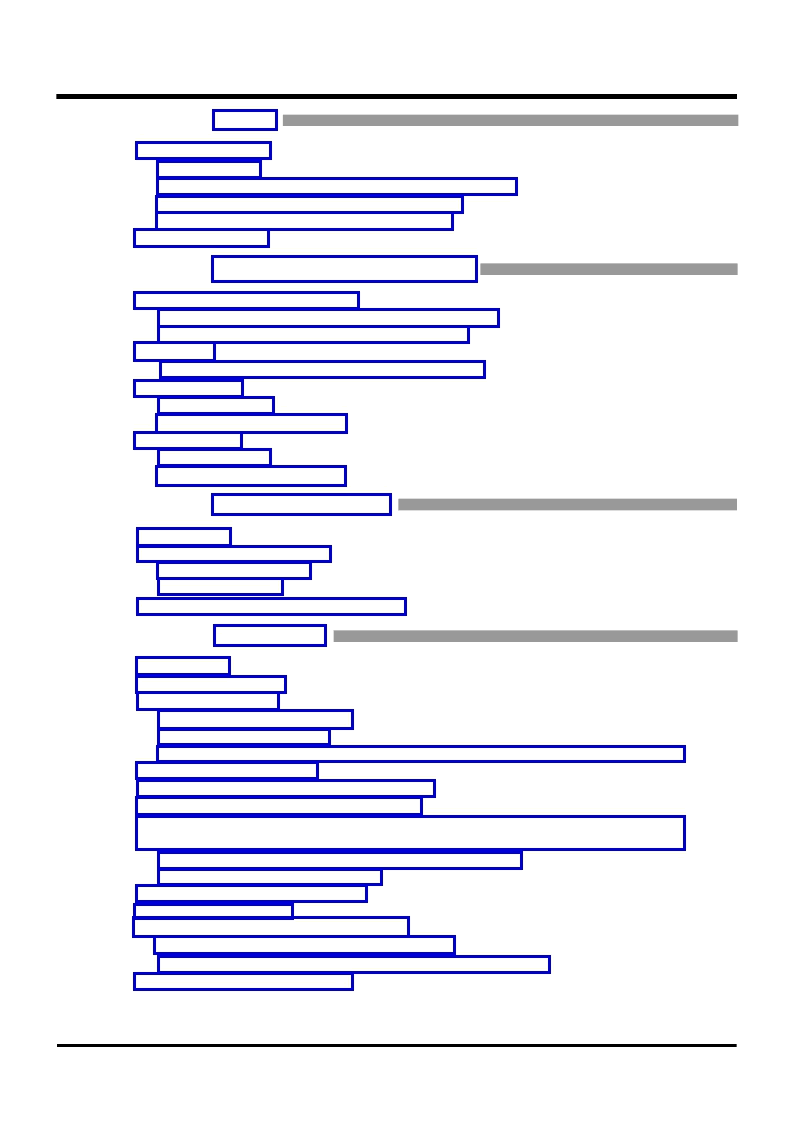
CHAPTER 4 RESET
4.1 Hardware reset ...................................................................................................................... 4-2
4.1.1 Pin state.......................................................................................................................... 4-3
4.1.2 State of CPU, SFR area, and internal RAM area..................................................... 4-4
4.1.3 Internal processing sequence after reset ................................................................. 4-11
4.1.4 Time supplying “L” level to RESET pin.................................................................... 4-12
4.2 Software reset...................................................................................................................... 4-13
CHAPTER 5 CLOCK GENERATING CIRCUIT
5.1 Oscillation circuit examples ............................................................................................... 5-2
5.1.1 Connection example using resonator/oscillator.......................................................... 5-2
5.1.2 Externally generated clock input example.................................................................. 5-2
5.2 Clocks.......................................................................................................................................5-3
5.2.1 Clocks generated in clock generating circuit ............................................................. 5-4
5.3 Stop mode .............................................................................................................................. 5-5
5.3.1 Stop mode ...................................................................................................................... 5-5
[Precautions for Stop mode] .................................................................................................. 5-8
5.4 Wait mode............................................................................................................................... 5-9
5.4.1 Wait mode ...................................................................................................................... 5-9
[Precautions for Wait mode]................................................................................................. 5-11
CHAPTER 6 INPUT/OUTPUT PINS
6.1 Overview ..................................................................................................................................6-2
6.2 Programmable I/O ports ...................................................................................................... 6-2
6.2.1 Direction register............................................................................................................ 6-3
6.2.2 Port register.................................................................................................................... 6-4
6.3 Examples of handling unused pins .................................................................................. 6-7
CHAPTER 7 INTERRUPTS
7.1 Overview ..................................................................................................................................7-2
7.2 Interrupt sources................................................................................................................... 7-4
7.3 Interrupt control .................................................................................................................... 7-5
7.3.1 Interrupt disable flag (I) ................................................................................................ 7-7
7.3.2 Interrupt request bit....................................................................................................... 7-7
7.3.3 Interrupt priority level select bits and processor interrupt priority level (IPL) .......7-7
7.4 Interrupt priority level.......................................................................................................... 7-9
7.5 Interrupt priority level detection circuit ........................................................................ 7-10
7.6 Interrupt priority level detection time ............................................................................ 7-12
7.7 Sequence from acceptance of interrupt request until execution of interrupt
routine.................................................................................................................................... 7-13
7.7.1 Change in IPL at acceptance of interrupt request..................................................7-14
7.7.2 Push operation for registers....................................................................................... 7-15
7.8 Return from interrupt routine........................................................................................... 7-16
7.9 Multiple interrupts............................................................................................................... 7-16
7.10 External interrupts (INTi interrupt) ............................................................................... 7-18
7.10.1 Functions of INTi interrupt request bit.................................................................... 7-20
7.10.2 Switching of INTi interrupt request occurrence factor ..........................................7-21
7.11 Precautions for interrupts............................................................................................... 7-22
相關PDF資料 |
PDF描述 |
|---|---|
| 772521 | BRENNER HALBMIKRO H88MM |
| 773-102 | PUSHWIRE CONNECTOR 2.5SQMM 2 |
| 773-104 | PUSHWIRE CONNECTOR 2.5SQMM 4 |
| 773-106 | PUSHWIRE CONNECTOR 2.5SQMM 6 |
| 773-108 | PUSHWIRE CONNECTOR 2.5SQMM 8 |
相關代理商/技術參數(shù) |
參數(shù)描述 |
|---|---|
| 772-1/2-BL | 制造商:Ideal Industries Inc 功能描述:HEAT SHRINK,THIN, 1/2" X 4 |
| 77210 | 制造商:Molex 功能描述: |
| 77210 SL001 | 功能描述:多芯電纜 20AWG 9C SHIELDED 1000FT SPOOL SLATE RoHS:否 制造商:Alpha Wire 導體數(shù)量:3 線規(guī) - 美國線規(guī)(AWG):16 絞合:19 x 29 屏蔽:Shielded 長度:100 ft 電壓額定值:600 V 外殼材料:Polytetrafluoroethylene (PTFE) 絕緣材料:Polytetrafluoroethylene (PTFE) 類型:Communication and Control |
| 77210 SL005 | 功能描述:多芯電纜 20AWG 9C SHIELDED 100FT SPOOL SLATE RoHS:否 制造商:Alpha Wire 導體數(shù)量:3 線規(guī) - 美國線規(guī)(AWG):16 絞合:19 x 29 屏蔽:Shielded 長度:100 ft 電壓額定值:600 V 外殼材料:Polytetrafluoroethylene (PTFE) 絕緣材料:Polytetrafluoroethylene (PTFE) 類型:Communication and Control |
| 77211 | 制造商:Molex 功能描述: |
發(fā)布緊急采購,3分鐘左右您將得到回復。