- 您現(xiàn)在的位置:買賣IC網(wǎng) > PDF目錄360597 > 92260 OVERHEAD IONISER 61CM PDF資料下載
參數(shù)資料
| 型號: | 92260 |
| 英文描述: | OVERHEAD IONISER 61CM |
| 中文描述: | 架空IONISER 61厘米 |
| 文件頁數(shù): | 4/6頁 |
| 文件大?。?/td> | 82K |
| 代理商: | 92260 |
PPE-5060.E
Page 4 of 6
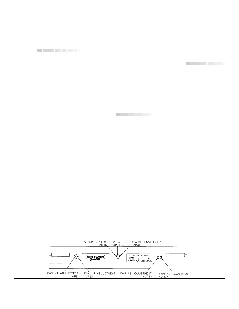
Figure 4. Calibrating C/E Ioniser
Unit 17. Millbrook Business Park, Sybron Way Crowborough, East Sussex TN6 3JZ United Kingdom
Phone: 00 44 (0) 1892-665313, Fax: 00 44 (0) 1892-668838 E-mail: info@charleswater.co.uk, Internet: www.charleswater.co.uk
ALARM JUMPER
- this jumper is
normally installed at the factory and
provides an audible alarm to
supplement the flashing red PWR light
when the unit needs cleaning. Some
units have a small switch in place of the
jumper.
Operation
After the unit is mounted securely and
connected to a properly wired outlet,
turn the key switch to the set position.
The performance of the ioniser is
directly related to the airflow on the area
to be protected. Generally, try to use
the highest setting possible without
disturbing the operator or the work in
process.
After allowing the unit to run for several
minutes, a charged plate monitor can be
used to check the balance and
performance. We recommend doing
this at the time of the initial installation,
so that data can be collected and saved
for future reference. Place the charged
plate directly under each fan and record
the float (balance) voltage. If all fans
are offset slightly in the same direction,
the “+” or “-” BAL buttons can be used
to correct the offset. If the balance
varies from a positive offset to a
negative offset between fans, the
individual fan zone controls can be
manipulated as required.
It is not uncommon to find differences
between ionisers from bench to bench
or even between fans on ionisers during
initial setup. This is often caused by the
presence of objects on or around the
bench. Large metal objects nearby or
machines or equipment on the bench
will often cause a shift in the offset
voltage at that area. The individual
zone controls of the C/E ionisers allow
this to be compensated for during initial
setup.
After balance offsets have been
checked, the decay performance of
each fan should be measured and
recorded. This information will be
useful to establish a maintenance
schedule. When decay times begin to
increase significantly, or if the red PWR
light begins to flash, emitter cleaning is
usually indicated. By recording the time
intervals between the first few
cleanings, a maintenance schedule can
be developed.
After initial setup and testing has been
done, the key switch can be set to the
LOCK position and normal workstation
use resumed.
If the ioniser is used in a manner not
specified by the manufacturer, the
protection provided by the ioniser
may be impaired.
Maintenance
By nature, all electric ionisers attract
contaminants to the high voltage emitter
pins. For best performance, this
contamination must be kept to a
minimum. This was a major factor in
the design process of the C/E ioniser.
Although we could not eliminate the
maintenance, we have made it far
easier and much cleaner than ever
before.
Turn the key switch to the OFF
position.
Grasp the cassette ejector levers at
the center and pivot outward about
90 degrees.
Grasping the right and left corners,
pull the cassette straight out of the
ioniser.
The cassettes can then be
replaced with a spare set or
removed to another area for
cleaning.
Cleaning of the cassette can be
accomplished with a stiff brush or
lint-free swab and isopropyl alcohol
or other residue-free cleaning
solvent.
The emitter cassettes or the
individual removable tungsten
emitters can also be cleaned in an
ultrasonic cleaning tank.
Calibration
See figure 4.
We recommend re-calibration every 12
months maximum, however, most users
will often choose a much shorter
interval, especially if the product being
worked on is very sensitive. On very
sensitive product, we recommend
checking the calibration any time an
emitter cassette is removed and
replaced.
Warning! Do not attempt to calibrate
this unit without proper equipment
such as a charged plate monitor.
Adjustments to the calibration
controls should be performed by
authorized trained personnel only.
Balance adjustment
Using a charge plate monitor, check
each fan's balance. Use the "BAL"
switches to zero the unit. If the fans are
a little out of balance with each other
use the fan adjustment pots to equalize
them. VR5,6 and VR1,2 on 122cm
model.
相關PDF資料 |
PDF描述 |
|---|---|
| 9226 | KABEL PARALLEL 36 ST / 36 BUCHSE 2M |
| 92270 | BRADY BOYS-OUT OF SERV Inhalt pro Packung: 2 Stk. |
| 256704 | Evaluation Kit for the MAX1213N, MAX1214N |
| 256705 | FLOOR STAND-DANGER |
| 256706 | Evaluation Kit for the MAX1213, MAX1214, MAX1215 |
相關代理商/技術參數(shù) |
參數(shù)描述 |
|---|---|
| 92261 | 功能描述:NUTDRIVER INCH W/CUSHION GRP 7/3 制造商:wiha 系列:* 零件狀態(tài):在售 標準包裝:1 |
| 9226-10368 | 制造商:Leach International Corporation 功能描述:CONTENT MANAGER - Bulk |
| 9226-10369 | 制造商:Leach International Corporation 功能描述:CONTACT PM FOR PRICING ** - Bulk |
| 922-6106-010 | 制造商: 功能描述: 制造商:undefined 功能描述: |
| 9226-10638 | 制造商:Leach International Corporation 功能描述:CONTENT MANAGER - Bulk |
發(fā)布緊急采購,3分鐘左右您將得到回復。