- 您現(xiàn)在的位置:買賣IC網(wǎng) > PDF目錄373856 > AD1315KZ (ANALOG DEVICES INC) High Speed Active Load with Inhibit Mode PDF資料下載
參數(shù)資料
| 型號: | AD1315KZ |
| 廠商: | ANALOG DEVICES INC |
| 元件分類: | 模擬信號調(diào)理 |
| 英文描述: | High Speed Active Load with Inhibit Mode |
| 中文描述: | SPECIALTY ANALOG CIRCUIT, CDSO16 |
| 封裝: | HERMETIC SEALED, CERAMIC, LCC-16 |
| 文件頁數(shù): | 3/8頁 |
| 文件大?。?/td> | 247K |
| 代理商: | AD1315KZ |
AD1315
–3–
REV. A
ABSOLUTE MAXIMUM RATINGS
1
Power Supply Voltage
+V
S
to GND . . . . . . . . . . . . . . . . . . . . . . . . . . . . . . . +12 V
–V
S
to GND . . . . . . . . . . . . . . . . . . . . . . . . . . . . . . . . –11 V
Difference from +V
S
to –V
S
. . . . . . . . . . . . . . . . . . . . . 16 V
Inputs
Difference from INH to
INH
. . . . . . . . . . . . . . . . . . . . . 5 V
INH,
INH
. . . . . . . . . . . . . . . . . .+V
S
– 13.4 V, –V
S
+ 11 V
V
COM
, V
DUT
. . . . . . . . . . . . . . . +V
S
– 13.1 V, –V
S
+ 13.2 V
I
OL
, I
OH
Program Voltage . . . . . . . . +V
S
– 15 V, –V
S
+ 15 V
Operating Temperature Range . . . . . . . . . . . . . . . 0 to +70
°
C
Storage Temperature Range . . . . . . . . . . . . –65
°
C to +125
°
C
Lead Temperature Range (Soldering 20 sec)
2
. . . . . . .+300
°
C
Pin
No.
Symbol
Function
1
2
3
4
5
6
7
8
9
10
11
12
13
14
15
16
I
OLRTN
V
COM
V
DUT
–V
S
I
OHRTN
I
OLPROG
LID
GND
I
OHPROG
N/C
N/C
N/C
+V
S
INH
INH
N/C
Logic Low Current Return
Communication Voltage
Load/Dot Connection
Negative Supply
Logic High Current Return
Logic Low Current Program Voltage
Lid Connection (Internal)
Ground
Logic High Current Program Voltage
No Connection
No Connection
No Connection
Positive Supply
Inhibit
Inhibit
No Connection
1
Stresses above those listed under Absolute Maximum Ratings may cause perma-
nent damage to the device. This is a stress rating only; functional operation of the
device at these or any other conditions above those indicated in the operational
sections of this specification is not implied. Exposure to absolute maximum rating
conditions for extended periods may affect device reliability.
2
To ensure lead coplanarity (
±
0.002 inches) and solderability, handling with bare
hands should be avoided and the device should be stored in an environment at
24
°
C,
±
5
°
C (75
°
F,
±
10
°
F) with relative humidity not to exceed 65%.
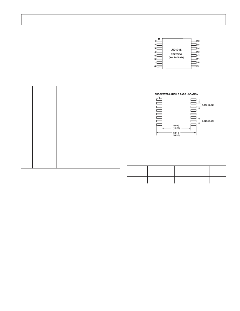
CONNECTION DIAGRAM
SUGGESTED PAD LOCATION
Dimensions shown in inches and (mm).
ORDERING GUIDE
Temperature
Range
Package
Description
Package
Option*
Model
AD1315KZ
0 to +70
°
C
16-Lead Gull Wing
Z-16B
*Z = Leaded Chip Carrier (Ceramic).
相關(guān)PDF資料 |
PDF描述 |
|---|---|
| AD1315 | High Speed Active Load with Inhibit Mode |
| AD1317 | Ultrahigh Speed Window Comparator with Latch |
| AD1317KZ | Ultrahigh Speed Window Comparator with Latch |
| AD1324KZ | Ultrahigh Speed Pin Driver with Inhibit Mode |
| AD1324 | Ultrahigh Speed Pin Driver with Inhibit Mode |
相關(guān)代理商/技術(shù)參數(shù) |
參數(shù)描述 |
|---|---|
| AD1317 | 制造商:AD 制造商全稱:Analog Devices 功能描述:Ultrahigh Speed Window Comparator with Latch |
| AD1317KZ | 制造商:Rochester Electronics LLC 功能描述:- Bulk |
| AD-1319-10 | 制造商:TE Connectivity 功能描述: |
| AD-1319-12-HOLDNG-FIXT | 制造商:TE Connectivity 功能描述:018579-000 |
| AD-1319-12-HOLDNG-FIXTURE | 制造商:TE Connectivity 功能描述:AD-1319-12-HOLDNG-FIXTURE |
發(fā)布緊急采購,3分鐘左右您將得到回復(fù)。