- 您現(xiàn)在的位置:買賣IC網(wǎng) > PDF目錄373859 > AD1815 (Analog Devices, Inc.) SoundComm Controller(SoundComm 控制器) PDF資料下載
參數(shù)資料
| 型號: | AD1815 |
| 廠商: | Analog Devices, Inc. |
| 英文描述: | SoundComm Controller(SoundComm 控制器) |
| 中文描述: | SoundComm控制器(SoundComm控制器) |
| 文件頁數(shù): | 34/44頁 |
| 文件大?。?/td> | 426K |
| 代理商: | AD1815 |
第1頁第2頁第3頁第4頁第5頁第6頁第7頁第8頁第9頁第10頁第11頁第12頁第13頁第14頁第15頁第16頁第17頁第18頁第19頁第20頁第21頁第22頁第23頁第24頁第25頁第26頁第27頁第28頁第29頁第30頁第31頁第32頁第33頁當前第34頁第35頁第36頁第37頁第38頁第39頁第40頁第41頁第42頁第43頁第44頁

AD1815
–34–
REV. 0
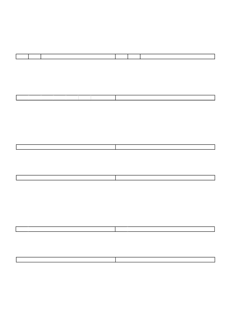
RS1M
LS1A [5:0]
LS1M
[07] I
2
S(0) ATTENUATION
7
6
LS0M
RES
Right I
2
S(1) Mute. 0 = Unmuted, 1 = Muted.
Left I
2
S(1) Attenuation register. T he LSB represents –1.5 dB, 000000 = 0 dB and the range is 0 dB to –94.5 dB.
Left I
2
S(1) Mute. 0 = Unmuted, 1 = Muted.
DEFAULT = [0x8080]
2
RS0A [5:0]
5
4
3
2
1
0
7
6
5
4
3
1
0
LS0A [5:0]
RS0M
RES
RS0A [5:0]
RS0M
LS0A [5:0]
LS0M
Right I
2
S(0) Attenuation register. T he LSB represents –1.5 dB, 000000 = 0 dB and the range is 0 dB to –94.5 dB.
Right I
2
S(0) Mute. 0 = Unmuted, 1 = Muted.
Left I
2
S(0) Attenuation register. T he LSB represents –1.5 dB, 000000 = 0 dB and the range is 0 dB to –94.5 dB.
Left I
2
S(0) Mute. 0 = Unmuted, 1 = Muted.
[08] PLAYBACK BASE COUNT
7
6
5
DEFAULT = [0x0000]
2
4
3
2
1
0
7
6
5
4
PBC [7:0]
3
1
0
PBC [15:8]
PBC [15:0]
Playback Base Count.T his register is for loading the Playback DMA Count. Writing a value to this register also
loads the same data into the Playback Current Count register. You must load this register when Playback Enable
(PEN) is de-asserted. When PEN is asserted, the Playback Current Count decrements once for every four-bytes
which are transferred via a DMA cycle. T he next transfer, after zero is reached in the Playback Current Count.
will generate an interrupt and will reload the Playback Current Count with the value in the Playback Base Count.
T he Playback Base Count should always be programmed to Number-Bytes divided by four, minus one ((Num-
ber-Bytes/4) –1). T he circular software DMA buffer must be divisible by four to ensure proper operation.
[09] PLAYBACK CURRENT COUNT
7
6
5
DEFAULT = [0x0000]
2
4
3
2
1
0
7
6
5
4
3
1
0
PCC [15:8]
PCC [7:0]
PCC [15:0]
Playback Current Count register. Contains the current Playback DMA Count. Reads and Writes must be done
when PEN is de-asserted.
[10] CAPTURE BASE COUNT
7
6
DEFAULT = [0x0000]
2
5
4
3
2
1
0
7
6
5
4
3
1
0
CBC [15:8]
CBC [7:0]
CBC [15:0]
Capture Base Count. T his register is for loading the Capture DMA Count. Writing a value to this register also
loads the same data into the Capture Current Count register. Loading must be done when Capture Enable
(CEN) is de-asserted. When CEN is asserted, the Capture Current Count decrements once for every four-bytes
which are transferred via a DMA cycle. T he next transfer, after zero is reached in the Capture Current Count,
will generate an interrupt and will reload the Capture Current Count with the value in the Capture Base Count.
T he Capture Base Count should always be programmed to Number-Bytes divided by four, minus one ((Number-
Bytes/4) –1). T he circular software DMA buffer must be divisible by four to ensure proper operation.
[11] CAPTURE CURRENT COUNT
7
6
5
DEFAULT = [0x0000]
2
4
3
2
1
0
7
6
5
4
3
1
0
CCC [15:8]
CCC [7:0]
CCC [15:0]
Capture Current Count register. Contains the current Capture DMA Count. Reading and Writing must be done
when CEN is de-asserted.
[12] TIMER BASE COUNT
7
6
DEFAULT = [0x0000]
2
5
4
3
2
1
0
7
6
5
4
3
1
0
T BC [15:8]
T BC [7:0]
T BC [15:0]
T imer Base Count. Register for loading the T imer Count. Writing a value to this register also loads the same data
into the T imer Current Count register. Loading must be done when T imer Enable (T E) is de-asserted. When T E
is asserted, the T imer Current Count register decrements once for every specified time period. T he time period
相關(guān)PDF資料 |
PDF描述 |
|---|---|
| AD1816AJS | SoundPort Controller |
| AD1816AJST | SoundPort Controller |
| AD1816A | SoundPort Controller(數(shù)字音頻的聲音端口控制器) |
| AD1818 | PCI SoundComm DC97 Digital Controller(PCI SoundComm DC97型數(shù)字控制器) |
| AD1819A | AC97 SoundPort Codec(AC97型聲音端口信號編解碼器) |
相關(guān)代理商/技術(shù)參數(shù) |
參數(shù)描述 |
|---|---|
| AD1815JS | 制造商:Rochester Electronics LLC 功能描述:- Bulk 制造商:Analog Devices 功能描述: |
| AD1816A | 制造商:AD 制造商全稱:Analog Devices 功能描述:SoundPort Controller |
| AD1816AJS | 制造商:AD 制造商全稱:Analog Devices 功能描述:SoundPort Controller |
| ad1816ajs-eeprom | 制造商:Rochester Electronics LLC 功能描述:AD1816A SOUND PORT CONTRO - Bulk 制造商:Analog Devices 功能描述: |
| AD1816AJST | 制造商:AD 制造商全稱:Analog Devices 功能描述:SoundPort Controller |
發(fā)布緊急采購,3分鐘左右您將得到回復(fù)。