- 您現(xiàn)在的位置:買賣IC網(wǎng) > PDF目錄373859 > AD1815 (Analog Devices, Inc.) SoundComm Controller(SoundComm 控制器) PDF資料下載
參數(shù)資料
| 型號: | AD1815 |
| 廠商: | Analog Devices, Inc. |
| 英文描述: | SoundComm Controller(SoundComm 控制器) |
| 中文描述: | SoundComm控制器(SoundComm控制器) |
| 文件頁數(shù): | 37/44頁 |
| 文件大?。?/td> | 426K |
| 代理商: | AD1815 |
第1頁第2頁第3頁第4頁第5頁第6頁第7頁第8頁第9頁第10頁第11頁第12頁第13頁第14頁第15頁第16頁第17頁第18頁第19頁第20頁第21頁第22頁第23頁第24頁第25頁第26頁第27頁第28頁第29頁第30頁第31頁第32頁第33頁第34頁第35頁第36頁當(dāng)前第37頁第38頁第39頁第40頁第41頁第42頁第43頁第44頁

AD1815
–37–
REV. 0
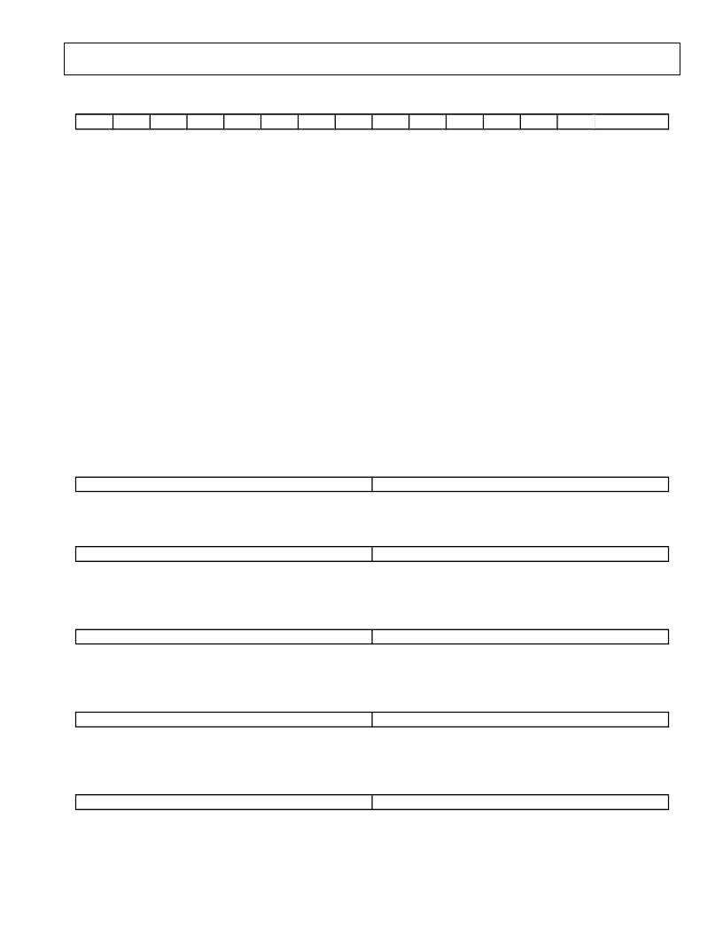
[33] DSP CONFIGURATION
7
6
DS1
DS0
DEFAULT = [0x0000]
2
DFS [2:0]
5
4
3
2
1
0
7
6
5
4
3
1
0
DIT
D M E
D MR
ADR
I1T
I0T
C PI
PBI
FMI
I1I
I0I
DFS [2:0]
DSP Frame Sync Source. Sets the DSP Port Frame Sync according to the following source.
000—Maximum Frame Rate
001—I
2
S(0) Sample Rate
010—I
2
S(1) Sample Rate
011—Music Synthesizer Sample Rate
100—Sound System Playback Sample Rate
101—Sound System Capture Sample Rate
111—Reserved
I
2
S(0) Data Intercept. 0 = Disable, 1 = Intercept I
2
S(0) Data Enabled.
I
2
S(1) Data Intercept. 0 = Disable, 1 = Intercept I
2
S(1) Data Enabled.
FM Music Synthesizer Data Intercept. 0 = Disable, 1 = Intercept FM Music Data Enabled.
Playback Data Intercept. 0 = Disable, 1 = Intercept Playback Data Enabled.
Capture Data Intercept. 0 = Disable, 1 = Intercept Capture Data Enabled.
I
2
S(0) T akeover Data. 0 = Disable, 1 = Enabled.
I
2
S(1) T akeover Data. 0 = Disable, 1 = Enabled.
Audio Resync. Writing “1” causes all FIFOs in the DSP port to be re-initialized.
DSP Modem Resync. Write to “1” to re-synchronize modem.
DSP Modem Enable. Set to “1” for DSP modem.
DSP Interrupt. A write to this bit causes an ISA interrupt if DIE is asserted.
DSP Mailbox 0 Status. 0 = last access indicates read, 1 = last access indicates write.
DSP Mailbox 1 Status. 0 = last access indicates read, 1 = last access indicates write.
I0I
I1I
FMI
PBI
CPI
I0T
I1T
ADR
DMR
DME
DIT
DS0
DS1
[34] FM SAMPLE RATE
7
6
DEFAULT = [0x5622]
2
5
4
3
2
1
0
7
6
5
4
3
1
0
FMSR [15:8]
FMSR [7:0]
FMSR [15:0] F Music Sample Rate register. T he sample rate can be programmed from 4 kHz to 27.6 kHz in 1 hertz increments.
[35] I
2
S(1) SAMPLE RATE
7
6
DEFAULT = [0xAC44]
2
5
4
3
2
1
0
7
6
5
4
3
1
0
S1SR [15:8]
S1SR [7:0]
S1SR [15:0]
I
2
S(1) Sample Rate register. T he sample rate can be programmed from 4 kHz to 55.2 kHz in 1 hertz increments.
Programming this register has no effect unless I
2
SF1 [1:0] is enabled.
[36] I
2
S(0) SAMPLE RATE
7
6
DEFAULT = [0xAC44]
2
5
4
3
2
1
0
7
6
5
4
3
1
0
S0SR [15:8]
S0SR [7:0]
S0SR [15:0]
I
2
S(0) Sample Rate register. T he sample rate can be programmed from 4 kHz to 55.2 kHz in 1 hertz increments.
Programing this register has no effect unless I
2
SF0 [1:0] is enabled.
[37] MODEM SAMPLE RATE
7
6
DEFAULT = [0x1C20]
2
5
4
3
2
1
0
7
6
5
4
3
1
0
MSR [15:8]
MSR [7:0]
MSR [15:0]
MODEM Sample Rate register. T he sample rate can be programmed from 4 kHz to 13.8 kHz in 1 hertz increments.
T his register is only valid when IME(ISA MODEM ENABLE) or DME(DSP MODEM ENABLE) is asserted.
[38] PROGRAMMABLE CLOCK RATE
7
6
5
PCR [15:8]
DEFAULT = [0xAC44]
2
4
3
2
1
0
7
6
5
4
PCR [7:0]
3
1
0
PCR [15:0]
Programmable Clock Rate register. T he clock rate can be programmed from 25 kHz to 50 kHz in 1 hertz
increments. T his register is only valid when the COF bits in SS[32] are set for the multiplier factor. PCLK O =
256
×
SS[38]/2
COF
. See SS[32] for determining the value of COF.
相關(guān)PDF資料 |
PDF描述 |
|---|---|
| AD1816AJS | SoundPort Controller |
| AD1816AJST | SoundPort Controller |
| AD1816A | SoundPort Controller(數(shù)字音頻的聲音端口控制器) |
| AD1818 | PCI SoundComm DC97 Digital Controller(PCI SoundComm DC97型數(shù)字控制器) |
| AD1819A | AC97 SoundPort Codec(AC97型聲音端口信號編解碼器) |
相關(guān)代理商/技術(shù)參數(shù) |
參數(shù)描述 |
|---|---|
| AD1815JS | 制造商:Rochester Electronics LLC 功能描述:- Bulk 制造商:Analog Devices 功能描述: |
| AD1816A | 制造商:AD 制造商全稱:Analog Devices 功能描述:SoundPort Controller |
| AD1816AJS | 制造商:AD 制造商全稱:Analog Devices 功能描述:SoundPort Controller |
| ad1816ajs-eeprom | 制造商:Rochester Electronics LLC 功能描述:AD1816A SOUND PORT CONTRO - Bulk 制造商:Analog Devices 功能描述: |
| AD1816AJST | 制造商:AD 制造商全稱:Analog Devices 功能描述:SoundPort Controller |
發(fā)布緊急采購,3分鐘左右您將得到回復(fù)。