- 您現(xiàn)在的位置:買賣IC網(wǎng) > PDF目錄378284 > ADC1241CMJ (NATIONAL SEMICONDUCTOR CORP) Self-Calibrating 12-Bit Plus Sign mP-Compatible A/D Converter with Sample-and-Hold PDF資料下載
參數(shù)資料
| 型號(hào): | ADC1241CMJ |
| 廠商: | NATIONAL SEMICONDUCTOR CORP |
| 元件分類: | ADC |
| 英文描述: | Self-Calibrating 12-Bit Plus Sign mP-Compatible A/D Converter with Sample-and-Hold |
| 中文描述: | 1-CH 12-BIT SUCCESSIVE APPROXIMATION ADC, PARALLEL ACCESS, CDIP28 |
| 封裝: | CERAMIC, DIP-28 |
| 文件頁數(shù): | 13/14頁 |
| 文件大?。?/td> | 268K |
| 代理商: | ADC1241CMJ |
4.0 Dynamic Performance
Many applications require the A/D converter to digitize ac
signals, but the standard dc integral and differential nonlin-
earity specifications will not accurately predict the A/D con-
verter’s performance with ac input signals. The important
specifications for ac applications reflect the converter’s abil-
ity to digitize ac signals without significant spectral errors
and without adding noise to the digitized signal. Dynamic
characteristics such as signal-to-noise
a
distortion ratio
(S/(N
a
D)), effective bits, full power bandwidth, aperture
time and aperture jitter are quantitative measures of the
A/D converter’s capability.
An A/D converter’s ac performance can be measured using
Fast Fourier Transform (FFT) methods. A sinusoidal wave-
form is applied to the A/D converter’s input, and the trans-
form is then performed on the digitized waveform. S/(N
a
D)
is calculated from the resulting FFT data, and a spectral plot
may also be obtained. Typical values for S/(N
a
D) are
shown in the table of Electrical Characteristics, and spectral
plots are included in the typical performance curves.
The A/D converter’s noise and distortion levels will change
with the frequency of the input signal, with more distortion
and noise occurring at higher signal frequencies. This can
be seen in the S/(N
a
D) versus frequency curves. These
curves will also give an indication of the full power band-
width (the frequency at which the S/(N
a
D) drops 3 dB).
Two sample/hold specifications, aperture time and aperture
jitter, are included in the Dynamic Characteristics table
since the ADC1241 has the ability to track and hold the
analog input voltage. Aperture time is the delay for the A/D
to respond to the hold command. In the case of the
ADC1241, the hold command is internally generated. When
the Auto-Zero function is not being used, the hold command
occurs at the end of the acquisition window, or seven clock
periods after the rising edge of the WR. The delay between
the internally generated hold command and the time that
the ADC1241 actually holds the input signal is the aperture
time. For the ADC1241, this time is typically 100 ns. Aper-
ture jitter is the change in the aperture time from sample to
sample. Aperture jitter is useful in determining the maximum
slew rate of the input signal for a given accuracy. For exam-
ple, an ADC1241 with 100 ps of aperture jitter operating with
a 5V reference can have an effective gain variation of about
1 LSB with an input signal whose slew rate is 12 V/
m
s.
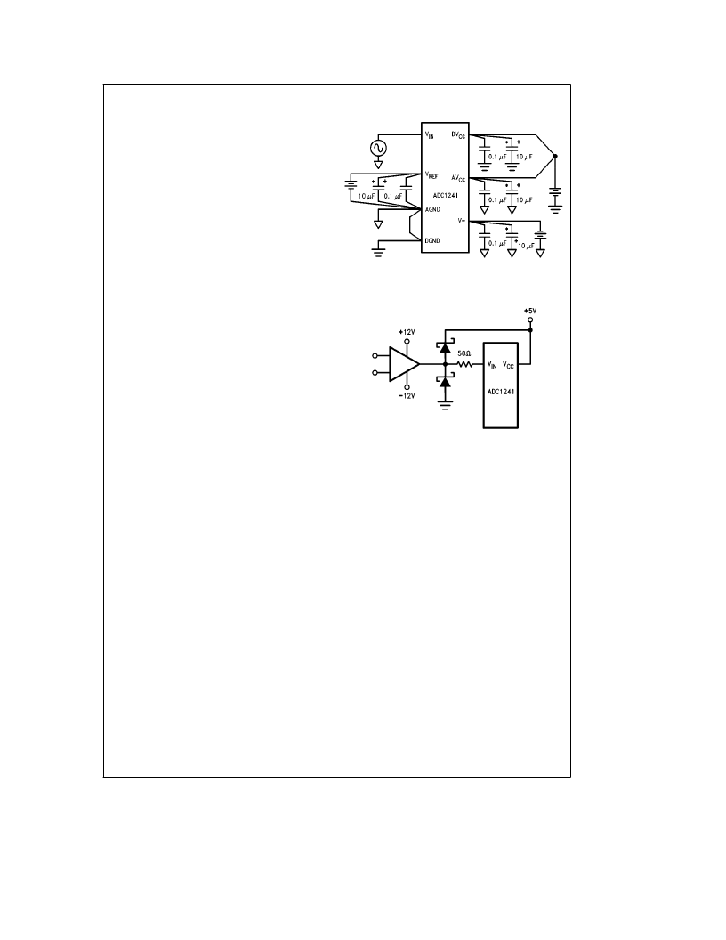
Power Supply Bypassing
TL/H/10554–19
*
Tantalum
Protecting the Analog Inputs
TL/H/10554–20
13
相關(guān)PDF資料 |
PDF描述 |
|---|---|
| ADC1241CIJ | Self-Calibrating 12-Bit Plus Sign mP-Compatible A/D Converter with Sample-and-Hold |
| ADC12441 | Dynamically-Tested Self-Calibrating 12-Bit Plus Sign A/D Converter with Sample-and-Hold(可自行校對(duì)的12位帶采樣和保持功能的A/D轉(zhuǎn)換器) |
| ADC12441883 | Dynamically-Tested Self-Calibrating 12-Bit Plus Sign A/D Converter with Sample-and-Hold |
| ADC12441CMJ | Dynamically-Tested Self-Calibrating 12-Bit Plus Sign A/D Converter with Sample-and-Hold |
| ADC12441CIJ | Dynamically-Tested Self-Calibrating 12-Bit Plus Sign A/D Converter with Sample-and-Hold |
相關(guān)代理商/技術(shù)參數(shù) |
參數(shù)描述 |
|---|---|
| ADC1242 | 制造商:未知廠家 制造商全稱:未知廠家 功能描述: |
| ADC1242CIJ | 制造商:NSC 制造商全稱:National Semiconductor 功能描述:12-Bit Plus Sign Sampling A/D Converter |
| ADC1243D125HD-C1 | 制造商:Integrated Device Technology Inc 功能描述:HLQFN56R - Bulk |
| ADC1243D160HD-C1 | 制造商:Integrated Device Technology Inc 功能描述:HLQFN56R - Bulk |
| ADC1243D200HD-C1 | 制造商:Integrated Device Technology Inc 功能描述:HLQFN56R - Bulk |
發(fā)布緊急采購,3分鐘左右您將得到回復(fù)。