- 您現(xiàn)在的位置:買賣IC網 > PDF目錄366551 > AM79C981 (Advanced Micro Devices, Inc.) Integrated Multiport Repeater Plus⑩ (IMR+⑩) PDF資料下載
參數(shù)資料
| 型號: | AM79C981 |
| 廠商: | Advanced Micro Devices, Inc. |
| 英文描述: | Integrated Multiport Repeater Plus⑩ (IMR+⑩) |
| 中文描述: | 綜合多端中繼器加⑩(死亡率⑩) |
| 文件頁數(shù): | 14/40頁 |
| 文件大小: | 347K |
| 代理商: | AM79C981 |
第1頁第2頁第3頁第4頁第5頁第6頁第7頁第8頁第9頁第10頁第11頁第12頁第13頁當前第14頁第15頁第16頁第17頁第18頁第19頁第20頁第21頁第22頁第23頁第24頁第25頁第26頁第27頁第28頁第29頁第30頁第31頁第32頁第33頁第34頁第35頁第36頁第37頁第38頁第39頁第40頁
AMD
PRELIMINARY
1–84
Am79C981
Management Port
The IMR+ device management functions are enabled
when the TEST pin is tied LOW. The management com-
mands are byte oriented data and are input serially on
the SI pin. Any responses generated during execution of
a management command are output serially in a byte-
oriented format by the IMR+ device on the SO pin. Both
the input and output data streams are clocked with the
rising edge of the SCLK pin. The serial command data
stream and any associated results data stream are
structured in a manner similar to the RS232 serial data
format, i.e., one Start Bit followed by eight Data Bits.
The externally generated clock at the SCLK pin can be
either a free running clock synchronized to the input bit
patterns or a series of individual transitions meeting the
setup and hold times with respect to the input bit pattern.
If the latter method is used, it is to be noted that 20 SCLK
clock transitions are required for proper execution of
management commands that produce SO data, and
that 14 SCLK clock transitions are needed to execute
management commands that do not produce SO data.
Management Commands
The following section details the operation of each man-
agement command available in the IMR+ chip. In all
cases, the individual bits in each command byte are
shown with the MSB on the left and the LSB on the right.
Data bytes are received and transmitted LSB first and
MSB last. See Table 2 for a summary of the manage-
ment commands.
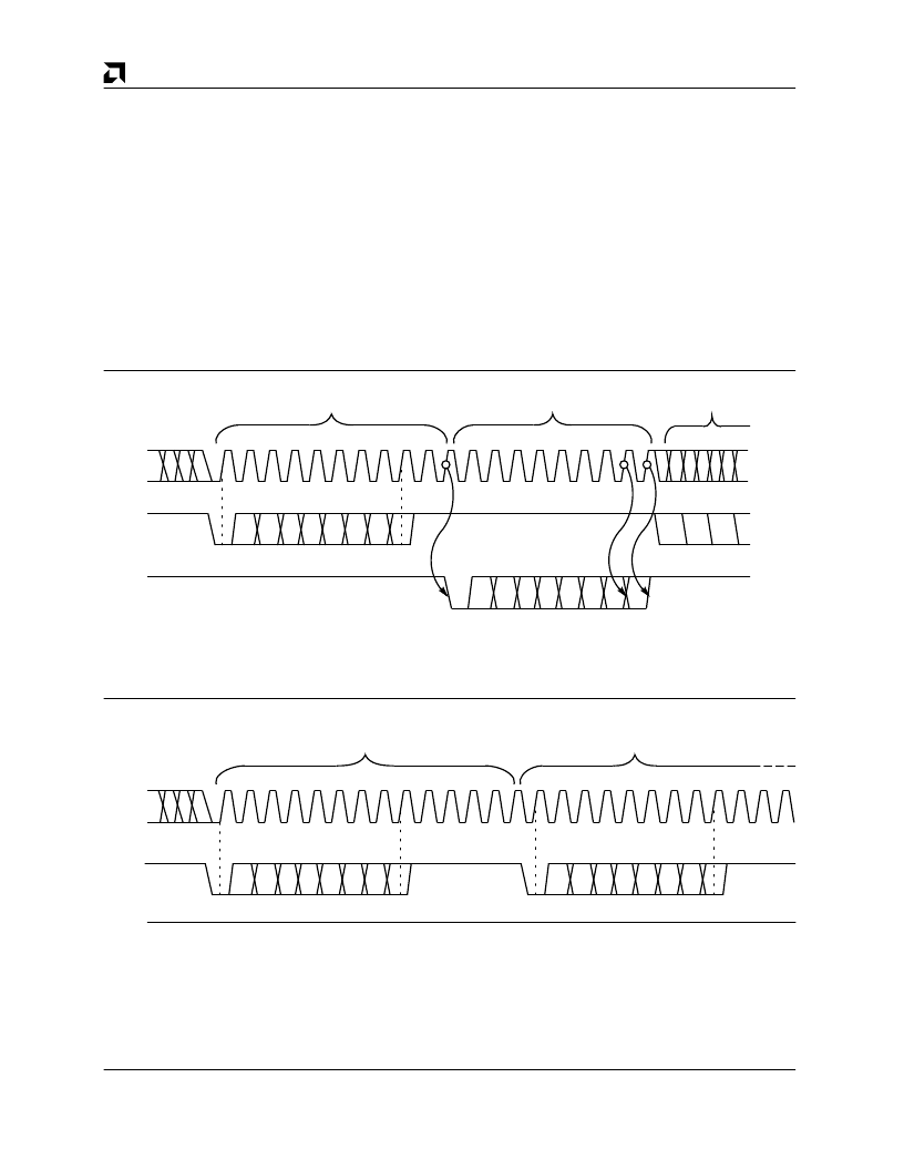
SCLK
SI
SO
STRT D0 D1 D2 D3 D4 D5 D6 D7
Command Execution Phase
Results Phase
STRT D0 D1 D2 D3 D4 D5 D6 D7
Next Command
17306B-17
Management Command/Response Timing
SCLK
SI
SO
Command Execution Phase
Next Command Execution Phase
STRT D0 D1 D2 D3 D4 D5 D6 D7
STRT D0 D1 D2 D3 D4 D5 D6 D7
17306B-18
Management Command Timing with No Response
相關PDF資料 |
PDF描述 |
|---|---|
| AM79C981JC | Integrated Multiport Repeater Plus⑩ (IMR+⑩) |
| AM79C982 | basic Integrated Multiport Repeater (bIMR) |
| AM79C982-4JC | basic Integrated Multiport Repeater (bIMR) |
| AM79C982-8JC | basic Integrated Multiport Repeater (bIMR) |
| AM79C983AKC | Integrated Multiport Repeater 2 (IMR2⑩) |
相關代理商/技術參數(shù) |
參數(shù)描述 |
|---|---|
| AM79C981JC | 制造商:AMD 制造商全稱:Advanced Micro Devices 功能描述:Integrated Multiport Repeater Plus⑩ (IMR+⑩) |
| AM79C982 | 制造商:AMD 制造商全稱:Advanced Micro Devices 功能描述:basic Integrated Multiport Repeater (bIMR) |
| AM79C982-4JC | 制造商:Advanced Micro Devices 功能描述:LAN HUB CONTROLLER, 84 Pin, PLCC |
| AM79C982-8JC | 制造商:AMD 制造商全稱:Advanced Micro Devices 功能描述:basic Integrated Multiport Repeater (bIMR) |
發(fā)布緊急采購,3分鐘左右您將得到回復。