- 您現(xiàn)在的位置:買賣IC網(wǎng) > PDF目錄379669 > AN221D04-EVAL (Electronic Theatre Controls, Inc.) Dynamically Reconfigurable FPAA With Enhanced I/O PDF資料下載
參數(shù)資料
| 型號: | AN221D04-EVAL |
| 廠商: | Electronic Theatre Controls, Inc. |
| 英文描述: | Dynamically Reconfigurable FPAA With Enhanced I/O |
| 中文描述: | 動態(tài)可重構(gòu)FPAA的具有增強(qiáng)的I / O |
| 文件頁數(shù): | 8/21頁 |
| 文件大小: | 448K |
| 代理商: | AN221D04-EVAL |
AN221E04 Datasheet – Dynamically Reconfigurable FPAA With Enhanced I/O
DS030100-U006a
- 8 -
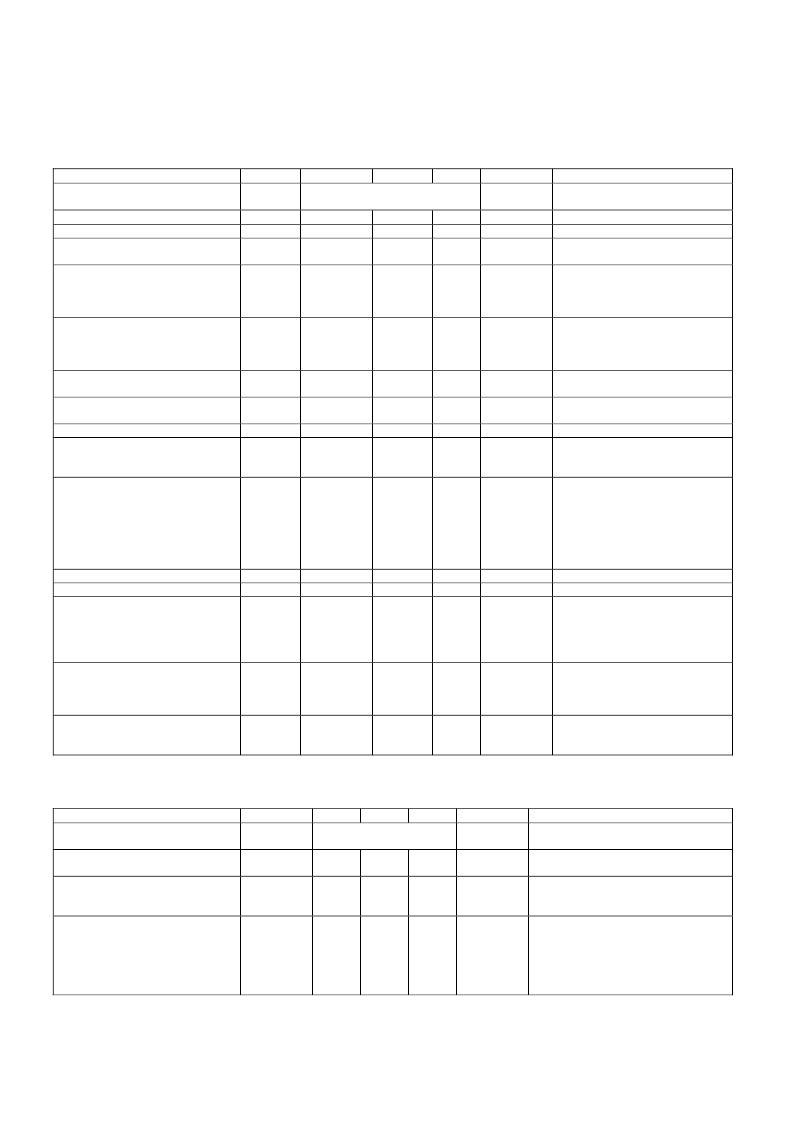
Input Differential Chopper Amplifier on and filter OFF
Parameter
Symbol
Vina
Vdiffina
Ginamp
Min
Typ
Max
Unit
Comment
Usable input range will be reduced
by the effective gain setting
Input Range
See analog input above
Gain Setting
Gain Accuracy
Gain Drift, (Temperature, Supply
Voltage and Time)
Chopper Frequency Clock Range
16
-
-
128
2.5
1.0
%
-
-
1.0
%
Fch
Fc/260100
-
>250
KHz
Fc = master clock frequency
Set Fch as slow as possible
Fch > 250KHz will result in some
signal attenuation
Chopper stabilized amplifier
The maximum value of 200μV is
guaranteed by production test
This is a tester limitation
Equivalent Input Offset Voltage
Vos
-
<100
200
μV
Offset Voltage Temperature
Coefficient
Power Supply Rejection Ratio
Voffsettc
-
0.5
2.0
μV/°C
from -40°C to 125°C
PSRR
65
-
-
dB
d.c.
a.c. See graphs on page 18
0.4v p-p Differential input at
660Hz
Gain setting = 16
Fch=Chopper clock frequency
The chopper frequency and
input frequency should be
chosen such that subsequent
low pass filtering can remove the
chopper stage frequency
elements
Input to filter or chopper
Input cell Gain = 16
Applies to Audio frequency
range Chopper clock Fch =
250KHz
See graphical data on page 18
Input signal = 285 mV p-p
differential,
Audio frequency range
See graphical data on page 18
Input signal =100 mV p-p
differential
See graphical data on page 18
Common Mode Rejection Ratio
CMRR
-
102
-
dB
Large Signal Harmonic Distortion
Dist
-
-40
-
dB
Input Frequency
Fain
0
Fch/20
Fch/2
KHz
Input Resistance
Input Capacitance
Input Referred Noise Figure
Rin
Cin
10
-
-
Mohm
pF
5.0
NF
-
0.09
-
μV/sqrtHz
Signal-to Noise Ratio and
Distortion
SINAD
-
75
-
dB
Spurious Free Dynamic Range
SFDR
-
74
-
dB
Input Differential Amplifier OFF and filter ON
Parameter
Symbol
Vina
Vdiffina
Min
Typ
Max
Unit
Comment
Input Range
See analog input above
Equivalent Input Offset
Vos
-
8
32
mV
Non-chopper stabilized input,
Filter corner frequency =470KHz
from -40°C to 125°C
I. measured at filter corner=470Khz
II. maximum at Filter corner=76KHz
Input filter frequency will define the
maximum frequency
Input filter is recommended to be
>30x higher than the max input
frequency, for 80dB distortion
performance
Offset Voltage Temperature
Coefficient
Voffsettc
-
0.05
I
1.0
II
mV/°C
Input Frequency
Fain
-
-
-
MHz
相關(guān)PDF資料 |
PDF描述 |
|---|---|
| AN221E04 | Dynamically Reconfigurable FPAA With Enhanced I/O |
| AN221E04-QFPSP | Dynamically Reconfigurable FPAA With Enhanced I/O |
| AN221E04-QFPTR | Dynamically Reconfigurable FPAA With Enhanced I/O |
| AN221E04-QFPTY | Dynamically Reconfigurable FPAA With Enhanced I/O |
| AN222 | AND / NOR circuit providing the logical function Q = NOT (A.B+C.D+E.F) |
相關(guān)代理商/技術(shù)參數(shù) |
參數(shù)描述 |
|---|---|
| AN221E04 | 制造商:未知廠家 制造商全稱:未知廠家 功能描述:Dynamically Reconfigurable FPAA With Enhanced I/O |
| AN221E04-E3-QFPTY | 制造商:Anadigm 功能描述:RECONFIGURABLE FPAA WITH RICH |
| AN221E04-QFPSP | 制造商:未知廠家 制造商全稱:未知廠家 功能描述:Dynamically Reconfigurable FPAA With Enhanced I/O |
| AN221E04-QFPTR | 制造商:未知廠家 制造商全稱:未知廠家 功能描述:Dynamically Reconfigurable FPAA With Enhanced I/O |
| AN221E04-QFPTY | 制造商:ANADIGM 功能描述: |
發(fā)布緊急采購,3分鐘左右您將得到回復(fù)。