- 您現(xiàn)在的位置:買賣IC網(wǎng) > PDF目錄362374 > APC08Y08-W Non-Isolated DC/DC Power Module PDF資料下載
參數(shù)資料
| 型號: | APC08Y08-W |
| 英文描述: | Non-Isolated DC/DC Power Module |
| 中文描述: | 非隔離DC / DC電源模塊 |
| 文件頁數(shù): | 9/23頁 |
| 文件大?。?/td> | 2632K |
| 代理商: | APC08Y08-W |
Technical Reference Note (APC08)
MODEL: APC08 SERIES
OCTOBER 4, 2004 - REVISION 03
SHEET 9 OF 23
Method 1: External Trim Resistor
(continued)
whichever is lower. By connecting an external resistor across P4 and P2, Vo is adjusted to a lower value. Only small
reductions, 2%, in voltage are recommended, as adjustment to lower voltages tends to affect the loop compensation of the
module.
Full range adjustment (from 0.9V to 3.6V) can be obtained from a module with the lowest Vo setpoint (0.9Vo).
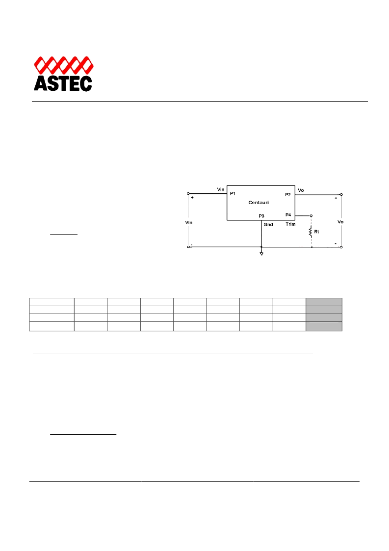
To adjust Vo to a higher value
, please refer to
Figure 4. The required resistor value (Rt) can be
determined through Equation (1) where Vo is the
voltage on P2 before the adjustment and Vot is the
voltage of P2 after Rt is connected.
Vref
Rt
Equation (1)
1
R
Vo
Vot
=
Please refer to related constants given in TABLE 1 to calculate the Equation.
TABLE 1. CONSTANTS
1.5V
4.32k
9.09k
APC08X03
APC08X08
V
r
/ V
ref
Be aware that the maximum Vo allowed is 3.6V (for APC08x08 series). Please refer to Centauri datasheet.
Example:
Module version: APC08J03-9 (1.8 to 6.0Vin, 0.9Vo).
Requiring to adjust output voltage from Vo = 0.9V to Vot = 1.8V. V
ref
= 0.875V and R
1
= 3.09k
(from TABLE 1).
Based on Equation (1), Rt can be determined as 3.0k
.
To adjust Vo to a lower value
, Rt should be connected between P4 and P2. Equation (2) provides the calculation for Rt.
)
)(
(
R
V
V
V
ot
o
ref
Note: minimum Vo = 0.9V
Version
R2
R2
0.87V
0.9V
97.6k
210k
1.2V
8.45k
17.4k
1.8V
2.94k
6.04k
2.5V
1.69k
3.48k
3.3V
1.13k
2.32k
R1
3.09k
6.49k
2
)
(
V
V
V
V
Rt
ref
ot
ref
o
=
Equation (2)
Figure 4. Output Voltage Trim Setup.
相關(guān)PDF資料 |
PDF描述 |
|---|---|
| APC12M08 | 40 Watts |
| APC12 | 40 Watts |
| APC12F03 | 40 Watts |
| APC12F08 | 40 Watts |
| APC12G03 | 40 Watts |
相關(guān)代理商/技術(shù)參數(shù) |
參數(shù)描述 |
|---|---|
| APC1 | 制造商:LUMINIS 制造商全稱:LUMINIS 功能描述:Attachment accessories |
| APC100SS | 功能描述:TOOL 制造商:astro tool corp 系列:- 零件狀態(tài):有效 工具類型:- 配套使用產(chǎn)品/相關(guān)產(chǎn)品:- 特性:- 標(biāo)準(zhǔn)包裝:1 |
| APC103 | 功能描述:TOOL 制造商:astro tool corp 系列:- 零件狀態(tài):有效 工具類型:- 配套使用產(chǎn)品/相關(guān)產(chǎn)品:- 特性:- 標(biāo)準(zhǔn)包裝:1 |
| APC103D/Z | 制造商:Assmann Electronics Inc 功能描述: |
| APC106 | 功能描述:TOOL 制造商:astro tool corp 系列:- 零件狀態(tài):有效 工具類型:- 配套使用產(chǎn)品/相關(guān)產(chǎn)品:- 特性:- 標(biāo)準(zhǔn)包裝:1 |
發(fā)布緊急采購,3分鐘左右您將得到回復(fù)。