- 您現(xiàn)在的位置:買賣IC網 > PDF目錄11006 > AS2540 (ams)IC TELEPHONE CMOS MULTIFU 28SOIC PDF資料下載
參數資料
| 型號: | AS2540 |
| 廠商: | ams |
| 文件頁數: | 16/19頁 |
| 文件大?。?/td> | 0K |
| 描述: | IC TELEPHONE CMOS MULTIFU 28SOIC |
| 標準包裝: | 27 |
| 系列: | * |
Data Sheet AS2540
austriamicrosystems
Revision 3.1
Page 5 of 18
The DC characteristic is determined by the voltage at LI
pin and a 30
resistor between LI and LS pin. It can be
calculated by the following equation: VLS = VLI + ILine *
30
. The t.m. voltage at the LI pin is 4.5V. The calculation
leads to the following DC resistances: 330
to 75 at line
currents from 15mA to 100mA.
2/4 wire conversion
AS2540 has a built-in dual Wheatstone bridge with one
common ground. This provides a maximum of
independence of AC impedance and side tone from each
other. One can adapt side tone without changing the AC
impedance.
A1=3.4/3.5
A2=-0.4
AC impedance
The ac impedance of AS2540 is set to t.m. 1000
. With
the external capacitor at CI pin it can be programmed
complex. With a parallel impedance at the LS pin it can be
programmed to 600
.
Side Tone
A good sidetone cancellation can be achieved by using the
following equation:
ZBAL/ZLINE = 10
Transmit path
The gain of the M1/M2 —> LS transmit path is set to 38dB
for ac-impedance 1000
. The input is differential with an
impedance of 25k
. The soft clip circuit limits the output
voltage at LS to 2Vp. The attack time is 30s/6dB and the
decay time is 20ms/6dB.
The gain of the TIT —> LS transmit path is set to 8dB for
ac-impedance 1000
. The input is single ended with an
impedance of 25k
. The soft clip circuit is not active for
this input. The dynamic range of this path is 2.5Vp at LS.
Receive path
The gain of the LS —> ROH receive path is set to 2dB for
ac-impedance 1000
. The receive input is the differential
signal of RI and STB. During DTMF dialling a MF comfort
tone is applied to ROH which is -30dB relative to the line
level. The soft clip circuit limits the output voltage at ROH
to 1Vp. It prevents harsh distortion and acoustic shock.
The gain of the LS —> ROT receive path is set to 0dB for
ac-impedance 1000
. The receive input is the differential
signal of RI and STB. The soft clip circuit is not active for
this output.
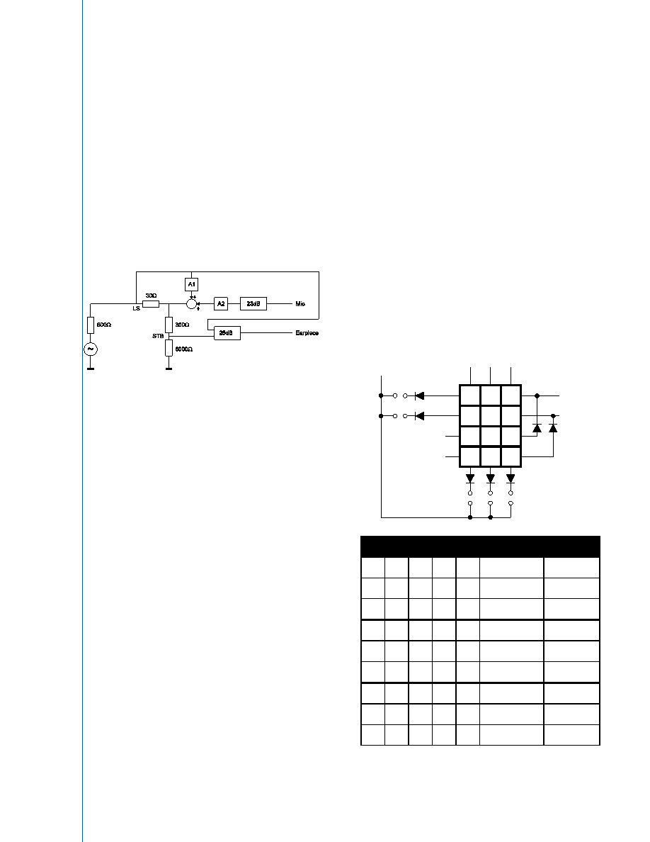
Modescan
The DTMF-level on the line and the function of the line loss
compensation can be selected with the connection of the
MODE-pin to the keyboard matrix. The MODE-pin is
scanned once after each OFF-Hook transition.
R1
1
PIN
C1
2
3
R2
4
5
6
7
8
9
*
0
#
PIN
C2
PIN
C3
PIN
R1
PIN
R2
PIN
MODE
c1
C2
C3
C2
C1
R2
R1
LLC
Dtmf Level
45mA-75mA
-6dBm
XX
45mA-75mA
-8dBm
X
45mA-75mA
-10dBm
X
20mA-50mA
-6dBm
X
20mA-50mA
-8dBm
XX
20mA-50mA
-10dBm
XX
No LLC
-6dBm
XX
No LLC
-8dBm
XX
X
No LLC
-10dBm
X indicates connection to pin mode
ams
AG
Technical
content
still
valid
相關PDF資料 |
PDF描述 |
|---|---|
| VI-B3Y-IV-S | CONVERTER MOD DC/DC 3.3V 99W |
| VI-200-IY-F3 | CONVERTER MOD DC/DC 5V 50W |
| XRT5683AID-F | IC PCM LINE INTERFACE 18SOIC |
| VI-B3V-IY-B1 | CONVERTER MOD DC/DC 5.8V 50W |
| XR2211ACD-F | IC FSK DEMOD/TONE DECOD 14SOIC |
相關代理商/技術參數 |
參數描述 |
|---|---|
| AS2540_04 | 制造商:AMSCO 制造商全稱:austriamicrosystems AG 功能描述:Remote Controlled Single-Chip-Telephone |
| AS2540-7R | 功能描述:EURO-CASSETTE 100W 2X 15V RoHS:否 類別:電源 - 外部/內部(非板載) >> DC DC Converters 系列:* 標準包裝:1 系列:Quint 類型:隔離 輸入電壓:24V 輸出:24V 輸出數:1 輸出 - 1 @ 電流(最大):24 VDC @ 50A 輸出 - 2 @ 電流(最大):- 輸出 - 3 @ 電流(最大):- 輸出 - 4 @ 電流(最大):- 功率(瓦特):1200W 安裝類型:底座安裝 工作溫度:0°C ~ 40°C 效率:- 封裝/外殼:模塊 尺寸/尺寸:4.33" L x 9.09" W x 6.14" H(110mm x 231mm x 156mm) 包裝:散裝 電源(瓦特)- 最大:1200W 批準:- 其它名稱:277-69722866365-NDQUINT-BAT/24DC/12AH |
| AS2540-9R | 制造商:Power-One 功能描述:DCDC - Bulk |
| AS2540Q | 制造商:AMSCO 制造商全稱:austriamicrosystems AG 功能描述:Remote Controlled Single-Chip-Telephone |
| AS2540T | 制造商:AMS 功能描述:REMOTE CNTRLD SNGL-CHIP TELE |
發(fā)布緊急采購,3分鐘左右您將得到回復。