- 您現(xiàn)在的位置:買賣IC網(wǎng) > PDF目錄11006 > AS2540 (ams)IC TELEPHONE CMOS MULTIFU 28SOIC PDF資料下載
參數(shù)資料
| 型號: | AS2540 |
| 廠商: | ams |
| 文件頁數(shù): | 19/19頁 |
| 文件大小: | 0K |
| 描述: | IC TELEPHONE CMOS MULTIFU 28SOIC |
| 標準包裝: | 27 |
| 系列: | * |
Data Sheet AS2540
austriamicrosystems
Revision 3.1
Page 8 of 18
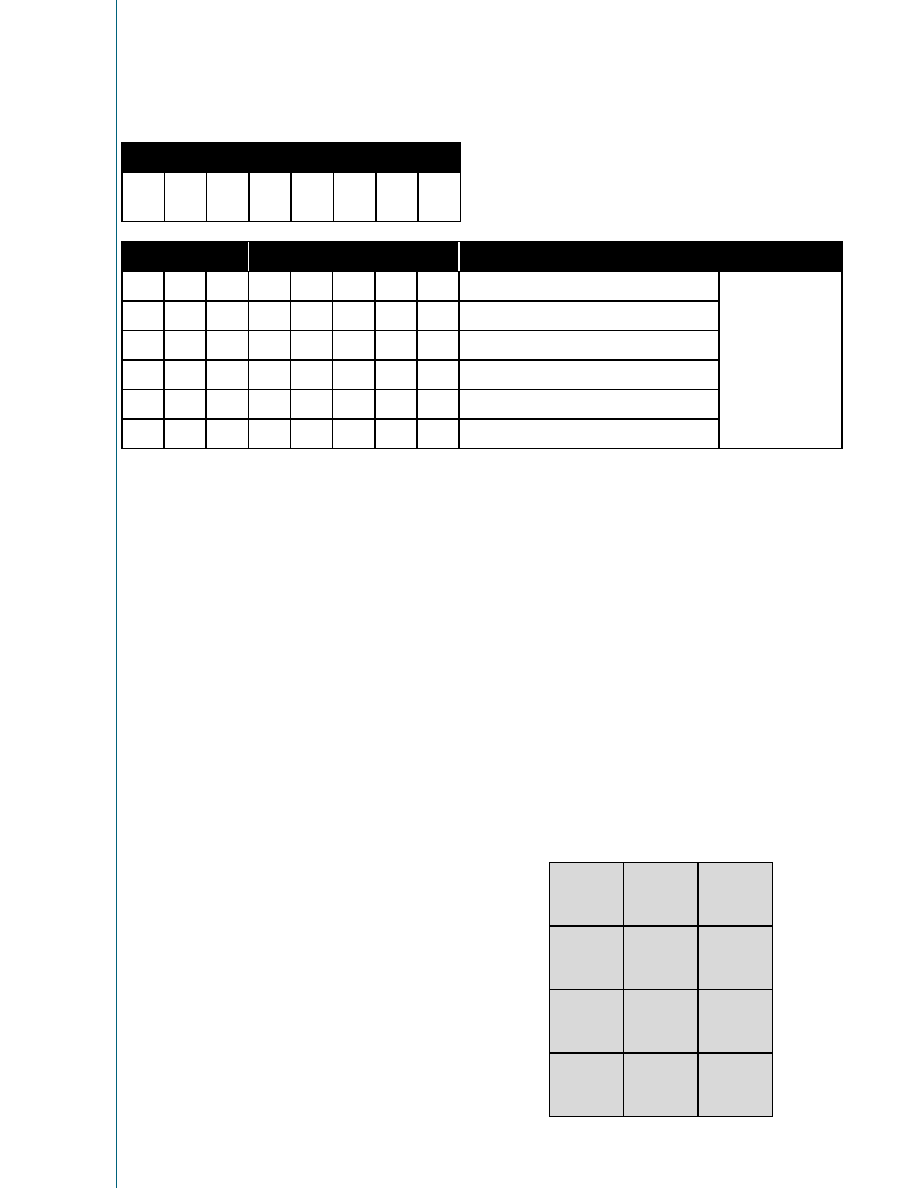
<Line Event> Message
<LineEvent> message format
b7
MSB
b6
b5
11111
LSB
b7
b6
b5
b4
b3
b2
b1
b0
Status
Remark
1
1
10
1
valid ring signal detected
0
1
10
1
no ring signal
1
1
10
1
manual hook switch - off-hook (pin MHS)
0
1
10
1
manual hook switch - on-hook (pin MHS)
1
1
10
1
electronic hook switch - off-hook (pin EHS)
0
1
10
1
electronic hook switch - on-hook (pin EHS)
Status of AS2540
Protocol
Line Events
AS2540 has 3 inputs, namely MHS (Manual Hook Switch),
EHS (Electronic Hook Switch) and RFD (Ring Frequency
Detector), which sense the state of the two hook-switches
and discriminate an applied ring signal. The MHS is
connected to the manual hook switch which is operated by
the handset and the EHS is connected to an electronic
hook switch which is operated by the CPU. Whenever the
state of these inputs changes, AS2540 immediately sends
<LineEvent> to the CPU after a debounce time. MHS and
EHS up-debouncing lasts 15ms, down-debouncing lasts
85ms. RFD start to discriminate the ring frequency
immediately but will send a <LineEvent> message with a
delay of 102ms. A status change of MHS and EHS pins
must not change the momentary selected path of the
speech network.
The <LineEvent>-message is sent without consideration of
the momentary activities of AS2540 in order to meet PTT
requirements (e.g. line break signalling). The code for the
<LineEvent>-message is chosen with regard to the
minimum current consumption in order to operate the
optocouplers. Pending <Ack>-messages will be queued
after the <LineEvent>-message. An already running
transmissions of <Ack> will not be interrupted and
<LineEvent> will be sent afterwards in this case.
-
Mode transitions
Idle
→
→ BM →
→
→ MPM →
→
→ Idle
AS2540 always starts up in backup mode and is prepared
to act like an independent dialler. <LineEvent> is sent to
the CPU and AS2540 remains in back-up mode until any
valid message is sent from the CPU. This makes sure that
a non-operable CPU does not disable basic dialling
functions.
-
Mode transition
MPM
→
→ BM
A watchdog timer is started after <LineEvent> and is reset
whenever AS2540 receives a message from the CPU via
the serial interface. If the CPU does not send any further
valid message within 2400ms, AS2540 goes back into
back-up mode, immediately locks the UART and remains in
backup mode till next on-hook.
Dialling Functions
DTMF
The DTMF generator provides 8 frequencies (in Hz):
1
11
697+1209
2
22
697+1336
3
33
697+1477
4
44
770+1209
5
55
770+1336
6
66
770+1477
7
77
852+1209
8
88
852+1336
9
99
852+1477
***
941+1209
0
00
941+1336
#
##
941+1477
ams
AG
Technical
content
still
valid
相關(guān)PDF資料 |
PDF描述 |
|---|---|
| VI-B3Y-IV-S | CONVERTER MOD DC/DC 3.3V 99W |
| VI-200-IY-F3 | CONVERTER MOD DC/DC 5V 50W |
| XRT5683AID-F | IC PCM LINE INTERFACE 18SOIC |
| VI-B3V-IY-B1 | CONVERTER MOD DC/DC 5.8V 50W |
| XR2211ACD-F | IC FSK DEMOD/TONE DECOD 14SOIC |
相關(guān)代理商/技術(shù)參數(shù) |
參數(shù)描述 |
|---|---|
| AS2540_04 | 制造商:AMSCO 制造商全稱:austriamicrosystems AG 功能描述:Remote Controlled Single-Chip-Telephone |
| AS2540-7R | 功能描述:EURO-CASSETTE 100W 2X 15V RoHS:否 類別:電源 - 外部/內(nèi)部(非板載) >> DC DC Converters 系列:* 標準包裝:1 系列:Quint 類型:隔離 輸入電壓:24V 輸出:24V 輸出數(shù):1 輸出 - 1 @ 電流(最大):24 VDC @ 50A 輸出 - 2 @ 電流(最大):- 輸出 - 3 @ 電流(最大):- 輸出 - 4 @ 電流(最大):- 功率(瓦特):1200W 安裝類型:底座安裝 工作溫度:0°C ~ 40°C 效率:- 封裝/外殼:模塊 尺寸/尺寸:4.33" L x 9.09" W x 6.14" H(110mm x 231mm x 156mm) 包裝:散裝 電源(瓦特)- 最大:1200W 批準:- 其它名稱:277-69722866365-NDQUINT-BAT/24DC/12AH |
| AS2540-9R | 制造商:Power-One 功能描述:DCDC - Bulk |
| AS2540Q | 制造商:AMSCO 制造商全稱:austriamicrosystems AG 功能描述:Remote Controlled Single-Chip-Telephone |
| AS2540T | 制造商:AMS 功能描述:REMOTE CNTRLD SNGL-CHIP TELE |
發(fā)布緊急采購,3分鐘左右您將得到回復(fù)。