- 您現(xiàn)在的位置:買賣IC網(wǎng) > PDF目錄64119 > ASDX100A24R-DO (HONEYWELL SENSING AND CONTROL) ABSOLUTE, PEIZORESISTIVE PRESSURE SENSOR, 0-100Psi, 2%, 19A-E66, RECTANGULAR, THROUGH HOLE MOUNT PDF資料下載
參數(shù)資料
| 型號(hào): | ASDX100A24R-DO |
| 廠商: | HONEYWELL SENSING AND CONTROL |
| 元件分類: | 壓力傳感器 |
| 英文描述: | ABSOLUTE, PEIZORESISTIVE PRESSURE SENSOR, 0-100Psi, 2%, 19A-E66, RECTANGULAR, THROUGH HOLE MOUNT |
| 封裝: | DIP-8 |
| 文件頁(yè)數(shù): | 2/6頁(yè) |
| 文件大?。?/td> | 296K |
| 代理商: | ASDX100A24R-DO |
Microstructure Pressure Sensors
0 psi to 1 psi through 0 psi to 100 psi
ASDX DO Series
2 Honeywell
Sensing and Control
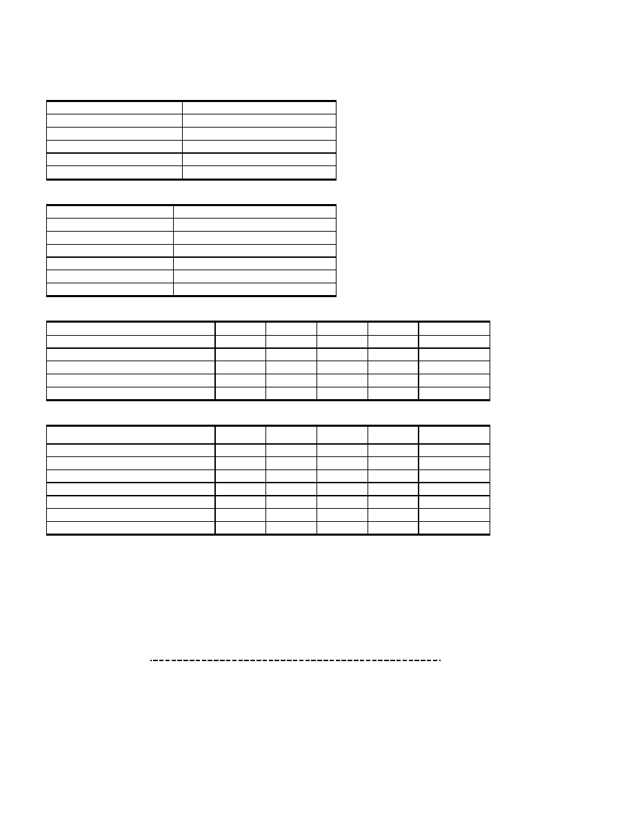
GENERAL SPECIFICATIONS
Supply Voltage (Vs)
4.75 Vdc to 5.25 Vdc
Maximum Supply Voltage*
6.50 Vdc max.
Current Consumption
6 mA typ.
Output current - sink
2 mA max.
Output current - source
2 mA max.
Lead Soldering Temperature
2 Sec to 4 Sec @ 250
°C [482 °F]
ENVIRONMENTAL SPECIFICATIONS (ALL DEVICES)
Temperature Ranges:
Compensated
0
°C to 85 °C [32 °F to 185 °F]
Operating
-20
°C to 105 °C [-4 °F to 221 °F]
Storage
-40
°C to 125 °C [-40 °F to 257 °F]
Vibration
10 g at 20 Hz to 2000 Hz
Shock
100 g for 11 ms
Life
1 Million cycles minimum
PERFORMANCE CHARACTERISTICS 4R DO
(1,5)
Characteristic
Symbol
Min.
Typ.
Max.
Units
Zero pressure offset
Hoff
158
19A
1DB
counts hex
Full scale span
(2)
Hfss
CCC
counts hex
Output at Full Scale Pressure
Hfso
E25
E66
EA8
counts hex
Accuracy
(3)
–
± 2.5
% H full scale
Response time
(4)
–
8
11
ms
PERFORMANCE CHARACTERISTICS 4D DO
(1,5)
Characteristic
Symbol
Min.
Typ.
(5)
Max.
Units
Zero pressure offset
Hoff
7BE
19A
1DB
counts hex
Full scale span
(2)
Hfss
CCC
counts hex
Output at Full Scale Pressure (P2)
(6)
Hfso
E25
E66
EA8
counts hex
Output at Full Scale Pressure (P1)
(6)
Hfso
158
19A
1DB
counts hex
Accuracy
(3)
–
± 2.0
% H full scale
Output Resolution
–
12
–
Bit
Response time
(4)
–
8
11
ms
Specification Notes:
Note 1:
Reference Conditions (unless otherwise noted): Supply voltage, VS=5.0
± 0.01 Vdc; Ta=25 °C [77 °F]. Output is ratiometric
within the supply voltage range (Vs).
Note 2:
Span is the algebraic difference between the output voltage at the specified pressure and the output at zero pressure. Span is
ratiometric to the supply voltage.
Note 3:
Accuracy is the combined errors from offset and span calibration, linearity, pressure hysteresis, and temperature effects.
Linearity is the measured deviation based on a straight line.
Hysteresis is the maximum output difference at any point within the operating pressure range for increasing and decreasing
pressure.
Calibration errors include the deviation of offset and full scale from nominal values.
Note 4:
Response time for 0 psi to full scale pressure step change, 10 % to 90 % rise time.
Note 5:
Read operation: Start, Slave Address, R/W =1, Data Byte 1 (MSB), Ackn Bit, Data Byte 2 (LSB).
The output is corrected pressure as unsigned 12 bits. Slave Address is F0h. Acknowledge Bit - pull data line LOW, master
generates an extra clock pulse for this purpose.
Note 6:
Output of the device when maximum positive pressure is applied on the backside (P2) or the front side (P1) of the sensing
element.
Note 7:
If maximum burst pressure is exceeded, even momentarily, the package may leak or burst, or the pressure sensing die may
fracture.
相關(guān)PDF資料 |
PDF描述 |
|---|---|
| ASDXL05D44D-DO | DIFFERENTIAL, PEIZORESISTIVE PRESSURE SENSOR, 0-0.18Psi, 2.5%, RECTANGULAR, THROUGH HOLE MOUNT |
| ASI10807 | UHF BAND, Si, NPN, RF SMALL SIGNAL TRANSISTOR |
| ASL670 | YAGI ANTENNA |
| ASL2010 | YAGI ANTENNA |
| ASP-1495 | 150 MHz - 512 MHz MOBILE STATION ANTENNA, 2.15 dBi GAIN |
相關(guān)代理商/技術(shù)參數(shù) |
參數(shù)描述 |
|---|---|
| ASDX100D24D | 制造商:未知廠家 制造商全稱:未知廠家 功能描述:0 TO 1 PSI THROUGH 0 TO 100 PSI PRESSURE TRANSDUCERS SenSym ICT |
| ASDX100D24H | 制造商:未知廠家 制造商全稱:未知廠家 功能描述:0 TO 1 PSI THROUGH 0 TO 100 PSI PRESSURE TRANSDUCERS SenSym ICT |
| ASDX100D24M | 制造商:未知廠家 制造商全稱:未知廠家 功能描述:0 TO 1 PSI THROUGH 0 TO 100 PSI PRESSURE TRANSDUCERS SenSym ICT |
| ASDX100D24R | 制造商:未知廠家 制造商全稱:未知廠家 功能描述:0 TO 1 PSI THROUGH 0 TO 100 PSI PRESSURE TRANSDUCERS SenSym ICT |
| ASDX100D44D | 功能描述:板上安裝壓力/力傳感器 ASDX RoHS:否 制造商:Honeywell 工作壓力:0 bar to 4 bar 壓力類型:Gage 準(zhǔn)確性:+ / - 0.25 % 輸出類型:Digital 安裝風(fēng)格:Through Hole 工作電源電壓:5 V 封裝 / 箱體:SIP 端口類型:Dual Radial Barbed, Same sides |
發(fā)布緊急采購(gòu),3分鐘左右您將得到回復(fù)。