- 您現(xiàn)在的位置:買賣IC網(wǎng) > PDF目錄379702 > AX88178 (Electronic Theatre Controls, Inc.) USB to 10/100/1000 Gigabit Ethernet/HomePNA Controller PDF資料下載
參數(shù)資料
| 型號: | AX88178 |
| 廠商: | Electronic Theatre Controls, Inc. |
| 英文描述: | USB to 10/100/1000 Gigabit Ethernet/HomePNA Controller |
| 中文描述: | USB接口10/100/1000千兆以太網(wǎng)/電話線網(wǎng)絡(luò)控制器 |
| 文件頁數(shù): | 5/35頁 |
| 文件大小: | 218K |
| 代理商: | AX88178 |
第1頁第2頁第3頁第4頁當(dāng)前第5頁第6頁第7頁第8頁第9頁第10頁第11頁第12頁第13頁第14頁第15頁第16頁第17頁第18頁第19頁第20頁第21頁第22頁第23頁第24頁第25頁第26頁第27頁第28頁第29頁第30頁第31頁第32頁第33頁第34頁第35頁
ASIX ELECTRONICS CORPORATION
5
AX88178 L
USB to 10/100/1000 Gigabit Ethernet/HomePNA Controller
2.0 Signal Description
The following abbreviations apply to the following pin description table.
I2
Input, 2.5V with 3.3V tolerant
I3
Input, 3.3V
I5
Input, 3.3V with 5V tolerant
O2
Output, 2.5V with 3.3V tolerant
O3
Output, 3.3V
O5
Output, 3.3V with 5V tolerant
B
Bi-directional I/O
B2
B5
PU
PD
P
S
Bi-directional I/O, 2.5V with 3.3V tolerant
Bi-directional I/O, 3.3V with 5V tolerant
Internal Pull Up (75K)
Internal Pull Down (75K)
Power Pin
Schmitt Trigger
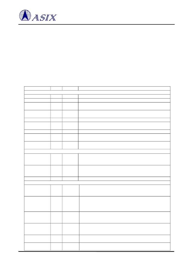
Table 1: Pinout Descripton
Pin Name
Type
Pin No
Pin Description
USB Interface
USB 2.0 data positive pin.
USB 2.0 data negative pin.
USB 1.1 data positive pin. Please connect to DP through a 39ohm
(+/-1%) serial resistor.
USB 1.1 data negative pin. Please connect to DM through a 39ohm
(+/-1%) serial resistor.
VBUS pin input. Please connect to USB bus power.
12Mhz crystal or oscillator clock input. This clock is needed for USB
PHY transceiver to operate.
12Mhz crystal or oscillator clock output.
For USB PHY’s internal biasing. Please connect to AGND through a
12.1Kohm (+/-1%) resistor.
For USB PHY’s internal biasing. Please connect to AVDD3 (3.3V)
through a 1.5Kohm (+/-5%) resistor.
Station Management Interface
Station Management Data Clock output. The timing reference for
MDIO. All data transfers on MDIO are synchronized to the rising edge
of this clock. The frequency of MDC is 1.5MHz.
Station Management Data Input/Output. Serial data input/output
transfers from/to the PHYs. The transfer protocol conforms to the
IEEE 802.3u MII spec.
Station Management Interrupt input.
MII/GMII/RGMII Interface
Receive Clock. RX_CLK is received from PHY to provide timing
reference for the transfer of RXD [7:0], RX_DV, and RX_ER signals
on receive direction of MII/GMII/RGMII interface.
114, 113,
112, 111,
110, 109,
108, 107
105
Receive Data Valid. RX_DV is driven synchronously with respect to
RX_CLK by PHY. It is asserted high when valid data is present on
RXD [7:0]. In RGMII mode, RX_DV acts as RX_CTL.
106
Receive Error. RX_ER is driven synchronously with respect to
RX_CLK by PHY. It is asserted high for one or more RX_CLK
periods to indicate to the MAC that an error has detected.
116
Collision Detected. COL is driven high by PHY when the collision is
detected.
115
Carrier Sense. CRS is asserted high asynchronously by the PHY when
either transmit or receive medium is non-idle.
DP
DM
DPRS
B
B
B
32
31
36
DMRS
B
35
VBUS
XIN12M
I5/PD/S
I3
10
26
XOUT12M
RREF
O3
I
27
30
RPU
I
34
MDC
O2
121
MDIO
B2/PU
120
MDINT
I2/PU
117
RX_CLK
I2
104
RXD [7:0]
I2
Receive Data. RXD [7:0] is driven synchronously with respect to
RX_CLK by PHY. In RGMII mode, only RXD [3:0] is used.
RX_DV
I2
RX_ER
I2
COL
I2
CRS
I2
相關(guān)PDF資料 |
PDF描述 |
|---|---|
| AX88178L | USB to 10/100/1000 Gigabit Ethernet/HomePNA Controller |
| AY-5-8116 | DUAL BAUD RATE GENERATOR |
| AY-5-8116T | DUAL BAUD RATE GENERATOR |
| AY-5-8136 | DUAL BAUD RATE GENERATOR |
| AY-5-8136T | DUAL BAUD RATE GENERATOR |
相關(guān)代理商/技術(shù)參數(shù) |
參數(shù)描述 |
|---|---|
| AX88178A | 制造商:ASIX 制造商全稱:ASIX 功能描述:AX88179 -- USB3.0 轉(zhuǎn) 10/100/1000M 千兆以太網(wǎng)控制芯片 |
| AX88178L | 制造商:ASIX 制造商全稱:ASIX 功能描述:USB to 10/100/1000 Gigabit Ethernet/HomePNA Controller |
| AX88179 | 制造商:ASIX 制造商全稱:ASIX 功能描述:AX88179 -- USB3.0 轉(zhuǎn) 10/100/1000M 千兆以太網(wǎng)控制芯片 |
| AX88179QF | 制造商:ASIX Electronics Corporation 功能描述: |
| AX88180 | 制造商:ASIX 制造商全稱:ASIX 功能描述:High-Performance Non-PCI 32-bit 10/100/1000M Gigabit Ethernet Controller |
發(fā)布緊急采購,3分鐘左右您將得到回復(fù)。