- 您現(xiàn)在的位置:買賣IC網(wǎng) > PDF目錄379702 > AX88178L (Electronic Theatre Controls, Inc.) USB to 10/100/1000 Gigabit Ethernet/HomePNA Controller PDF資料下載
參數(shù)資料
| 型號: | AX88178L |
| 廠商: | Electronic Theatre Controls, Inc. |
| 英文描述: | USB to 10/100/1000 Gigabit Ethernet/HomePNA Controller |
| 中文描述: | USB接口10/100/1000千兆以太網(wǎng)/電話線網(wǎng)絡(luò)控制器 |
| 文件頁數(shù): | 25/35頁 |
| 文件大小: | 218K |
| 代理商: | AX88178L |
第1頁第2頁第3頁第4頁第5頁第6頁第7頁第8頁第9頁第10頁第11頁第12頁第13頁第14頁第15頁第16頁第17頁第18頁第19頁第20頁第21頁第22頁第23頁第24頁當前第25頁第26頁第27頁第28頁第29頁第30頁第31頁第32頁第33頁第34頁第35頁
ASIX ELECTRONICS CORPORATION
25
AX88178 L
USB to 10/100/1000 Gigabit Ethernet/HomePNA Controller
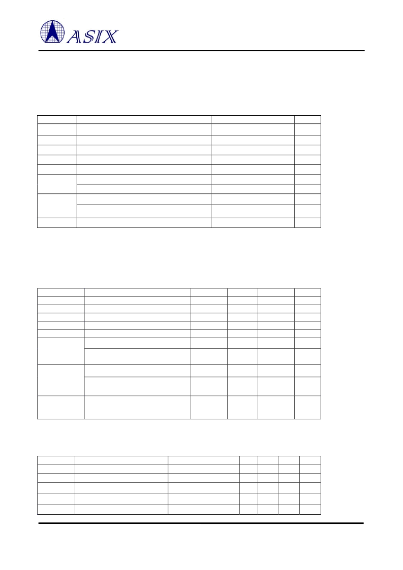
7.0 Electrical Specifications
7.1 DC Characteristics
7.1.1 Absolute Maximum Ratings
Symbol
VDDK
Digital core power supply
Parameter
Rating
Unit
V
- 0.3 to VDDK + 0.3
VDD2
VDD3
AVDDK
AVDD3
V
IN2
Power supply of 2.5V I/O
Power supply of 3.3V I/O
Analog core power supply
Power supply of analog I/O
Input voltage of 2.5V I/O
Input voltage of 2.5V I/O with 3.3V tolerant
Input voltage of 3.3V I/O
Input voltage of 3.3V I/O with 5V tolerant
- 0.3 to VDD2 + 0.3
- 0.5 to VDD3 + 0.5
- 0.3 to AVDDK + 0.3
- 0.5 to AVDD3 + 0.5
- 0.3 to VDD2 + 0.3
- 0.3 to 3.9
- 0.3 to VDD3 + 0.3
- 0.3 to 5.5
V
V
V
V
V
V
V
V
V
IN3
T
STG
Storage temperature
- 40 to 150
℃
Note: Permanent device damage may occur if absolute maximum ratings are exceeded. Functional operation should be
restricted in the optional sections of this datasheet. Exposure to absolute maximum rating condition for extended periods
may affect device reliability.
7.1.2 Recommended Operating Condition
Symbol
Parameter
VDDK
Digital core power supply
VDD2
Power supply of 2.5V I/O
VDD3
Power supply of 3.3V I/O
AVDDK
Analog core power supply
AVDD3
Power supply of analog I/O
Input voltage of 2.5 V I/O
V
IN2
Input voltage of 2.5 V I/O with 3.3 V
tolerance
Input voltage of 3.3 V I/O
V
IN3
Min
2.25
2.25
3.0
2.25
3.0
0
0
Typ
2.5
2.5
3.3
2.5
3.3
2.5
2.5
Max
2.75
2.75
3.6
2.75
3.6
2.75
3.6
Unit
V
V
V
V
V
V
V
0
3.3
3.6
V
Input voltage of 3.3 V I/O with 5 V
tolerance
Commercial junction operating
temperature
0
3.3
5.25
V
T
j
0
-
115
℃
7.1.3 Leakage Current and Capacitance
Symbol
Parameter
I
IN
Input current
I
OZ
Tri-state leakage current
C
IN
Input capacitance
C
OUT
Output capacitance
Condition
Min
-10
-10
-
-
Typ
±
1
±
1
3.1
3.1
Max
10
10
-
-
Unit
μ
A
μ
A
pF
pF
No pull-up or pull-down
C
BID
Bi-directional buffer capacitance
-
3.1
-
pF
相關(guān)PDF資料 |
PDF描述 |
|---|---|
| AY-5-8116 | DUAL BAUD RATE GENERATOR |
| AY-5-8116T | DUAL BAUD RATE GENERATOR |
| AY-5-8136 | DUAL BAUD RATE GENERATOR |
| AY-5-8136T | DUAL BAUD RATE GENERATOR |
| AY5-8116 | DUAL BAUD RATE GENERATOR |
相關(guān)代理商/技術(shù)參數(shù) |
參數(shù)描述 |
|---|---|
| AX88179 | 制造商:ASIX 制造商全稱:ASIX 功能描述:AX88179 -- USB3.0 轉(zhuǎn) 10/100/1000M 千兆以太網(wǎng)控制芯片 |
| AX88179QF | 制造商:ASIX Electronics Corporation 功能描述: |
| AX88180 | 制造商:ASIX 制造商全稱:ASIX 功能描述:High-Performance Non-PCI 32-bit 10/100/1000M Gigabit Ethernet Controller |
| AX88180LF | 制造商:ASIX 功能描述:NON PCI MAC CONTROLLER 10/100/1000 |
| AX88190 | 制造商:未知廠家 制造商全稱:未知廠家 功能描述:PCMCIA Fast Ethernet MAC Controller |
發(fā)布緊急采購,3分鐘左右您將得到回復(fù)。