- 您現(xiàn)在的位置:買賣IC網(wǎng) > PDF目錄295161 > BQ24630RGET (TEXAS INSTRUMENTS INC) SWITCHED CAPACITOR CONVERTER, PQCC24 PDF資料下載
參數(shù)資料
| 型號(hào): | BQ24630RGET |
| 廠商: | TEXAS INSTRUMENTS INC |
| 元件分類: | 穩(wěn)壓器 |
| 英文描述: | SWITCHED CAPACITOR CONVERTER, PQCC24 |
| 封裝: | 4 X 4 MM, GREEN, PLASTIC, VQFN-24 |
| 文件頁(yè)數(shù): | 30/33頁(yè) |
| 文件大小: | 1893K |
| 代理商: | BQ24630RGET |
第1頁(yè)第2頁(yè)第3頁(yè)第4頁(yè)第5頁(yè)第6頁(yè)第7頁(yè)第8頁(yè)第9頁(yè)第10頁(yè)第11頁(yè)第12頁(yè)第13頁(yè)第14頁(yè)第15頁(yè)第16頁(yè)第17頁(yè)第18頁(yè)第19頁(yè)第20頁(yè)第21頁(yè)第22頁(yè)第23頁(yè)第24頁(yè)第25頁(yè)第26頁(yè)第27頁(yè)第28頁(yè)第29頁(yè)當(dāng)前第30頁(yè)第31頁(yè)第32頁(yè)第33頁(yè)
SLUS894 – JANUARY 2010
www.ti.com
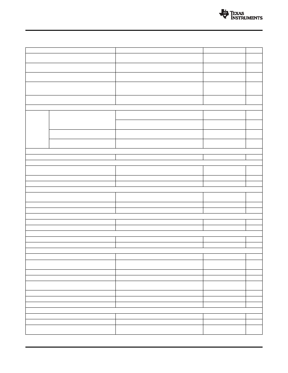
ELECTRICAL CHARACTERISTICS (continued)
5.0V
≤ V(VCC) ≤28V, 0°C<TJ<+125°C,typical values are at TA=25°C, with respect to GND unless otherwise noted
PARAMETER
TEST CONDITIONS
MIN
TYP
MAX
UNIT
Deglitch time for Temperature Out of
VTS > VLTF, or VTS < VTCO, or VTS < VHTF
400
ms
Range Detection
Deglitch time for Temperature in Valid
VTS < VLTF – VLTF_HYS or VTS >VTCO, or VTS > VHTF
20
ms
Range Detection
Deglitch time for current reduction to
VTS > VCOOL, or VTS < VWARM
25
ms
ICHARGE/8 due to warm or cool temperature
Deglitch time to charge at ICHARGE from
ICHARGE/8 when resuming from warm or
VTS < VCOOL - VCOOL_HYS, or VTS > VWARM - VWARM_HYS
25
ms
cool temperatures
Charge current due to warm or cool
VCOOL < VTS < VLTF, or VWARM < VTS < VHTF, or VWARM <
ICHARGE
temperatures
VTS < VTCO
/8
CHARGE OVER-CURRENT COMPARATOR (CYCLE-BY-CYCLE)
Current rising, in non-synchronous mode, mesure on
45.5
mV
V(SRP-SRN), VSRP < 2 V
Charge over-current falling threshold
Current rising, as percentage of V(IREG_CHG), in
160%
synchronous mode, VSRP > 2.2V
VOC
Minimum OCP threshold in synchronous mode, measure
Charge over-current threshold floor
50
mV
on V(SRP-SRN), VSRP > 2.2V
Maximum OCP threshold in synchronous mode, measure
Charge over-current threshold ceiling
180
mV
on V(SRP-SRN), VSRP > 2.2V
CHARGE UNDER-CURRENT COMPARATOR (CYCLE-BY-CYCLE)
VISYNSET
Charge under-current falling threshold
Switch from SYNCH to NON-SYNCH, VSRP > 2.2V
1
5
9
mV
BATTERY SHORTED COMPARATOR (BATSHORT)
BAT Short falling threshold, forced
VBATSHT
VSRP falling
2
V
non-synchronous mode
VBATSHT_HYS
BAT short rising hysteresis
200
mV
VBATSHT_DEG
Deglitch on both edge
1
ms
LOW CHARGE CURRENT COMPARATOR
Average low charge current falling
Measure on V(SRP-SRN), forced into non-synchronous
VLC
1.25
mV
threshold
mode
VLC_HYS
Low charge current rising hysteresis
1.25
mV
VLC_DEG
Deglitch on both edge
1
ms
VREF REGULATOR
VVREF_REG
VREF regulator voltage
VVCC > VUVLO, ( 0 – 35mA load)
3.267
3.3
3.333
V
IVREF_LIM
VREF current limit
VVREF = 0 V, VVCC > VUVLO
35
mA
REGN REGULATOR
VREGN_REG
REGN regulator voltage
VVCC > 10 V, CE = HIGH (0 – 40mA load)
5.7
6.0
6.3
V
IREGN_LIM
REGN current limit
VREGN = 0 V, VVCC > VUVLO
40
mA
TTC INPUT
TPRECHG
Precharge time before fault occurs
1440
1800
2160
sec
Precharge safety timer range(1)
Fast charge saftey timer range, with +/-
TCHARGE
Tchg = CTTC × KTTC
1
10
Hr
10% accuracy(1)
Fast charge timer accuracy(1)
0.047 mF ≤ CTTC ≤ 0.47 mF
–10%
10%
KTTC
Timer multiplier
1.4
min/nF
VTTC below this threshold disables the safety timer and
TTC low threshold
0.4
V
termination
TTC comparator high threshold
1.5
V
TTC comparator low threshold
1
V
TTC source/sink current
45
50
55
mA
BATTERY SWITCH (BATFET) DRIVER
RDS_BAT_OFF
BATFET turn-off resistance
VACN > 5V
150
RDS_BAT_ON
BATFET turn-on resistance
VACN > 5V
20
k
VBATDRV_REG = VACN – VBATDRV when VACN > 5V and
VBATDRV_REG
BATFET drive voltage
4.2
7
V
BATFET is on
(1)
Verified by design
6
Copyright 2010, Texas Instruments Incorporated
Product Folder Link(s): bq24630
相關(guān)PDF資料 |
PDF描述 |
|---|---|
| BQ25070DQCR | 1 A BATTERY CHARGE CONTROLLER, PDSO10 |
| BQ3285ESSNTR | 1 TIMER(S), REAL TIME CLOCK, PDSO24 |
| BQ3285ESS-N | 1 TIMER(S), REAL TIME CLOCK, PDSO24 |
| BQ3285ESSN | 1 TIMER(S), REAL TIME CLOCK, PDSO24 |
| BQ3285LCSS | 1 TIMER(S), REAL TIME CLOCK, PDSO24 |
相關(guān)代理商/技術(shù)參數(shù) |
參數(shù)描述 |
|---|---|
| BQ24630RGET | 制造商:Texas Instruments 功能描述:BATTERY CHARGER IC |
| BQ24640EVM | 功能描述:電源管理IC開發(fā)工具 Eval Mod for BQ24640 RoHS:否 制造商:Maxim Integrated 產(chǎn)品:Evaluation Kits 類型:Battery Management 工具用于評(píng)估:MAX17710GB 輸入電壓: 輸出電壓:1.8 V |
| BQ24640RVAR | 功能描述:電池管理 Hi Eff Synch Sw-Mode Batt Charge Cntrlr RoHS:否 制造商:Texas Instruments 電池類型:Li-Ion 輸出電壓:5 V 輸出電流:4.5 A 工作電源電壓:3.9 V to 17 V 最大工作溫度:+ 85 C 最小工作溫度:- 40 C 封裝 / 箱體:VQFN-24 封裝:Reel |
| BQ24640RVAT | 功能描述:電池管理 Hi Eff Synch Sw-Mode Batt Charge Cntrlr RoHS:否 制造商:Texas Instruments 電池類型:Li-Ion 輸出電壓:5 V 輸出電流:4.5 A 工作電源電壓:3.9 V to 17 V 最大工作溫度:+ 85 C 最小工作溫度:- 40 C 封裝 / 箱體:VQFN-24 封裝:Reel |
| BQ24650EVM-639 | 功能描述:電源管理IC開發(fā)工具 BQ24650 Eval Mod RoHS:否 制造商:Maxim Integrated 產(chǎn)品:Evaluation Kits 類型:Battery Management 工具用于評(píng)估:MAX17710GB 輸入電壓: 輸出電壓:1.8 V |
發(fā)布緊急采購(gòu),3分鐘左右您將得到回復(fù)。