- 您現(xiàn)在的位置:買賣IC網(wǎng) > PDF目錄366628 > C9531CY Single bilateral switch PDF資料下載
參數(shù)資料
| 型號: | C9531CY |
| 英文描述: | Single bilateral switch |
| 中文描述: | CPU系統(tǒng)時鐘發(fā)生器| SSOP封裝| 28腳|塑料 |
| 文件頁數(shù): | 5/14頁 |
| 文件大?。?/td> | 176K |
| 代理商: | C9531CY |

PCIX I/O System Clock Generator With EMI Control Features
Cypress Semiconductor Corporation
525 Los Coches St.
Milpitas, CA 95035. Tel: 408-263-6300, Fax: 408-263-6571
http://www.cypress.com
Document#: 38-07034 Rev. **
05/02/2001
Page 5 of 14
APPROVED PRODUCT
C9531
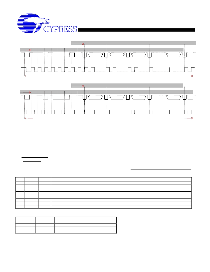
START CONDITION
Transmit
Receive
STOP CONDITION
START CONDITION
Transmit
Receiv
STOP CONDITION
1
8
ACK
MSB
0
0
0
SDATA
0
1
LSB
COMMAND BYTE
1
SCLK
1
BYTE N
8
8
8
BYTE 0
BYTE COUNT
ACK
ACK
ACK
ACK
(Don't Care)
(Don't Care)
(Valid)
(Valid)
Fig.5a
(WRITE)
(Valid)
SDATA
1
0
(Valid)
0
1
1
8
BYTE N
(Valid)
BYTE COUNT
SCLK
LSB
ACK
8
ACK
ACK
8
0
BYTE1
1
ACK
ACK
MSB
8
1
(Valid)
BYTE 0
Fig.5b (READ)
Fig.5
Serial Control Registers
NOTE:
The Pin# column lists the affected pin number where applicable. The @Pup column gives the state at true
power up. Bytes are set to the values shown only after true power up event occurs.
Following the acknowledge of the Address Byte (D2), two additional bytes must be sent:
1) “
Command Code
“
byte, and
2) “
Byte Count
” byte.
Although the data (bits) in these two bytes are considered “don’t care”; they must be sent and will be acknowledged.
Byte 0: Function Select Register
Bit
@Pup
7
1
6
0
5
1
4
0
3
0
2
0
1
0
0
1
Pin#
-
15
-
7
6
-
-
-
Description
Test Mode Enable. 1=normal operation, 0 = Test mode
Spread Spectrum modulation control bit (effective only when Bit 0 of this register is set to a 0) 0=OFF, 1=ON
SSCG Spread width select. 1 = 0.5%, 0 = 1.0% See Table below for clarification
S1 Bank A MSB frequency control bit (effective only when Bit 0 of this register is set to a 0)
S0 Bank A LSB frequency control bit (effective only when Bit 0 of this register is set to a 0)
Not used
Not used
Hardware/SMBus frequency control. 1=Hardware (pins 6, 7, and 15), 0=SMBus Byte 0 bits 3, 4, and 6
Clarification Table for Byte0, bit5
Byte 0, bit6
Byte0, bit5
0
0
1
1
Description
Frequency generated from second PLL
Frequency generated from XIN
Spread @ -1.0%
Spread @ -0.5%
0
1
0
1
相關(guān)PDF資料 |
PDF描述 |
|---|---|
| C9531 | SMD LED Lamps |
| C9706AY | ST92141 - 8/16 BIT MCU FOR 3-PHASE AC MOTOR CONTROL |
| C9726AY | ST92141 - 8/16 BIT MCU FOR 3-PHASE AC MOTOR CONTROL |
| C9801CY | Hex buffer |
| C9805CYB | Quad line receivers |
相關(guān)代理商/技術(shù)參數(shù) |
參數(shù)描述 |
|---|---|
| C9536-01 | 制造商:HAMAMATSU 制造商全稱:Hamamatsu Corporation 功能描述:UV POWER METER |
| C-9536-BAE | 功能描述:電池座、電池扣和電池接頭 2(AA) BATTERY HOLDER CUSTOM NCNR RoHS:否 制造商:Eagle Plastic Devices 產(chǎn)品:Battery Snaps 電池組電池大小:9 V 電池數(shù)量:1 端接類型:Snaps 顏色:Black 材料:Polyvinyl Chloride (PVC) 安裝風(fēng)格:Snap-In |
| C9537-4-2 | 制造商:CALFAX (ALCOA) 功能描述: |
| C9538-4 | 制造商:MISC. COMMERCIAL HRD 功能描述: 制造商:MISCELLANEOUS 功能描述: |
| C953P | 制造商:PERKINELMER 制造商全稱:PerkinElmer Optoelectronics 功能描述:CHANNEL PHOTO MULTIPLIER |
發(fā)布緊急采購,3分鐘左右您將得到回復(fù)。