- 您現(xiàn)在的位置:買賣IC網(wǎng) > PDF目錄366636 > CA3130S3 TRANSIL PDF資料下載
參數(shù)資料
| 型號: | CA3130S3 |
| 英文描述: | TRANSIL |
| 中文描述: | 電壓反饋運(yùn)算放大器 |
| 文件頁數(shù): | 14/15頁 |
| 文件大?。?/td> | 617K |
| 代理商: | CA3130S3 |
2-121
CA3130, CA3130A
Error-Amplifier in Regulated-Power Supplies
The CA3130 is an ideal choice for error-amplifier service in
regulated power supplies since it can function as an error-
amplifier when the regulated output voltage is required to
approach zero. Figure 20 shows the schematic diagram of a
40mA power supply capable of providing regulated output
voltage by continuous adjustment over the range from 0 to
13 volts. Q3 and Q4 in lC2 (a CA3086 transistor-array lC)
function as zeners to provide supply-voltage for the CA3130
comparator (IC1). Q1, Q2, and Q5 in IC2 are configured as a
low impedance, temperature-compensated source of adjust-
able reference voltage for the error amplifier. Transistors Q1,
Q2, Q3, and Q4 in lC3 (another CA3086 transistor-array lC)
are connected in parallel as the series-pass element. Tran-
sistor Q5 in lC3 functions as a current-limiting device by
diverting base drive from the series-pass transistors, in
accordance with the adjustment of resistor R2.
Figure 21 contains the schematic diagram of a regulated
power-supply capable of providing regulated output voltage
by continuous adjustment over the range from 0.1 to 50 volts
and currents up to 1 ampere. The error amplifier (lC1) and
circuitry associated with lC2 function as previously
described, although the output of lC1 is boosted by a dis-
crete transistor (Q4) to provide adequate base drive for the
Darlington-connected series-pass transistors Q1, Q2. Tran-
sistor Q3 functions in the previously described current-limit-
ing circuit.
Multivibrators
The exceptionally high input resistance presented by the
CA3130 is an attractive feature for multivibrator circuit
design because it permits the use of timing circuits with high
R/C ratios. The circuit diagram of a pulse generator (astable
multivibrator), with provisions for independent control of the
“on” and “off” periods, is shown in Figure 22. Resistors R1
and R2 are used to bias the CA3130 to the mid-point of the
supply-voltage and R3 is the feedback resistor. The pulse
repetition rate is selected by positioning S1 to the desired
position and the rate remains essentially constant when the
resistors which determine “on-period” and “off-period” are
adjusted.
Function Generator
Figure 23 contains a schematic diagram of a function gener-
ator using the CA3130 in the integrator and threshold detec-
tor functions. This circuit generates a triangular or square-
wave output that can be swept over a 1,000,000:1 range (0.1
Hz to 100 kHz) by means of a single control, R1. A voltage-
control input is also available for remote sweep-control.
The heart of the frequency-determining system is an opera-
tional-transconductance-amplifier (OTA)*, lC1, operated as a
voltage-controlled current-source. The output, I
O
, is a current
applied directly to the integrating capacitor, C1, in the feed-
back loop of the integrator lC2, using a CA3130, to provide
the triangular-wave output. Potentiometer R2 is used to
adjust the circuit for slope symmetry of positive-going and
negative-going signal excursions.
Another CA3130, IC3, is used as a controlled switch to set
the excursion limits of the triangular output from the integra-
tor circuit. Capacitor C2 is a “peaking adjustment” to opti-
mize the high-frequency square-wave performance of the
circuit.
Potentiometer R3 is adjustable to perfect the “amplitude
symmetry” of the square-wave output signals. Output from
the threshold detector is fed back via resistor R4 to the input
of lC1 so as to toggle the current source from plus to minus
in generating the linear triangular wave.
Operation with Output-Stage Power-Booster
The current-sourcing and-sinking capability of the CA3130
output stage is easily supplemented to provide power-boost
capability. In the circuit of Figure 24, three CMOS transistor-
pairs in a single CA3600E* lC array are shown parallel con-
nected with the output stage in the CA3130. In the Class A
mode of CA3600E shown, a typical device consumes 20 mA
of supply current at 15V operation. This arrangement boosts
the current-handling capability of the CA3130 output stage
by about 2.5X.
The amplifier circuit in Figure 24 employs feedback to estab-
lish a closed-loop gain of 48 dB. The typical large-signal
bandwidth (-3dB) is 50 kHz.
* See File Number 619 for technical information.
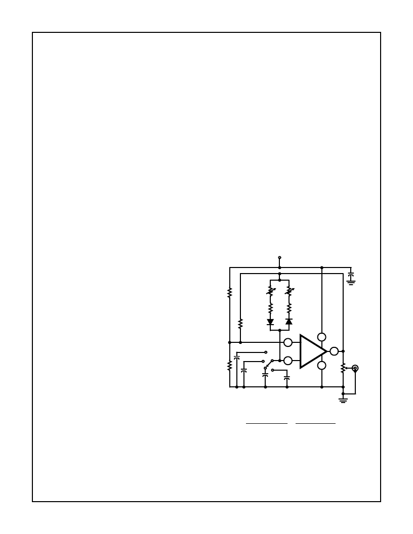
FIGURE 22. PULSE GENERATOR (ASTABLE MULTIVIBRATOR)
WITH PROVISIONS FOR INDEPENDENT CON-
TROL OF “ON” AND “OFF” PERIODS.
FREQUENCY RANGE:
POSITION OF SI
0.001
μ
F
0.01
μ
F
0.1
μ
F
1
μ
F
PULSE PERIOD
4
μ
s to 1ms
40
μ
s to 10ms
0.4
μ
s to 100ms
4
μ
s to 1s
7
4
6
3
2
R1
100k
R2
100k
R3
100k
ON-PERIOD
ADJUST
1M
2k
2k
OFF-PERIOD
ADJUST
1M
+15V
0.01
μ
F
OUTPUT
2k
0.001
μ
F
0.01
μ
F
0.1
μ
F
1
μ
F
SI
CA3130
+
-
相關(guān)PDF資料 |
PDF描述 |
|---|---|
| CA3130SX | TRANSIL |
| CA3138 | High-Current, High-Beta N-P-N Transistor Arrays |
| CA3138A | High-Current, High-Beta N-P-N Transistor Arrays |
| CA3160BT | Operational Amplifier |
| CA3094AH | 16A TRIACS |
相關(guān)代理商/技術(shù)參數(shù) |
參數(shù)描述 |
|---|---|
| CA3130SX | 制造商:Harris Corporation 功能描述: 制造商:Intersil Corporation 功能描述: |
| CA3130T | 制造商:RCA 功能描述: |
| CA3138 | 制造商:GESS 制造商全稱:GESS 功能描述:High-Current, High-Beta N-P-N Transistor Arrays |
| CA3138A | 制造商:GESS 制造商全稱:GESS 功能描述:High-Current, High-Beta N-P-N Transistor Arrays |
| CA3139 | 制造商:未知廠家 制造商全稱:未知廠家 功能描述:電視自動(dòng)調(diào)諧電路 |
發(fā)布緊急采購,3分鐘左右您將得到回復(fù)。