- 您現(xiàn)在的位置:買(mǎi)賣(mài)IC網(wǎng) > PDF目錄201420 > CG3020-7DB 3-OUTPUT 25 W DC-DC REG PWR SUPPLY MODULE PDF資料下載
參數(shù)資料
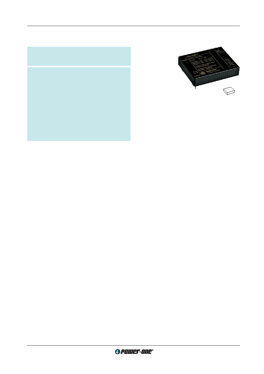
| 型號(hào): | CG3020-7DB |
| 元件分類: | 電源模塊 |
| 英文描述: | 3-OUTPUT 25 W DC-DC REG PWR SUPPLY MODULE |
| 文件頁(yè)數(shù): | 1/16頁(yè) |
| 文件大小: | 283K |
| 代理商: | CG3020-7DB |
當(dāng)前第1頁(yè)第2頁(yè)第3頁(yè)第4頁(yè)第5頁(yè)第6頁(yè)第7頁(yè)第8頁(yè)第9頁(yè)第10頁(yè)第11頁(yè)第12頁(yè)第13頁(yè)第14頁(yè)第15頁(yè)第16頁(yè)
Board Mountable
DC-DC Converters
G Series
Edition 5/5.2000
1/16
Very high efficiency, typ. 87%
Operating case temperature range –25...95
°C
Flex power (flexible load distribution on all outputs)
Excellent dynamic response (magnetic feedback)
Active current sharing for operation in parallel
Outputs overload, no-load and short-circuit proof
Serial 8 bit status communication interface
Thermal protection with pre-warning prior to shut-
down
Very compact (chip and wire technology)
High reliability
MTBF >700'000 h (Ground benign, 40
°C)
Table of Contents
Page
Summary .......................................................................... 1
Type Survey and Key Data .............................................. 2
Type Key .......................................................................... 2
Functional Description ...................................................... 3
Electrical Input Data ......................................................... 4
Electrical Output Data ...................................................... 5
25 Watt DC-DC Converters
G Series
Summary
The G series of 25 Watt DC-DC converters represents a
versalite range of board mountable power supplies for use
in advanced electronic systems of centralized or decentral-
ized structure. Features include very high efficiency com-
bined with compact size, high reliability (MTBF), wide input
voltage ranges, transient voltage and surge protection, low
output ripple and noise and excellent dynamic response to
load and line changes.
Available with three outputs electrically isolated from the in-
put the converters deliver 25 Watt output power with flexible
load distribution between all outputs without provoking un-
acceptable voltage deviations.
The G series is designed as a hybrid circuit comprising pro-
prietary control ASICs and chip and wire technology.
Page
Auxiliary Functions ........................................................... 8
Electromagnetic Compatibility (EMC) ............................ 10
Immunity to Environmental Conditions ........................... 11
Mechanical Data ............................................................ 12
Safety and Installation Instructions ................................ 12
Description of Options .................................................... 14
53
2.1"
43
1.69"
10.5
0.41"
The design is based on an advanced zero-voltage switch-
ing topology, optimised circuitry and high grade compo-
nents including the latest integration technologies.
Main application areas are telecom, avionics, industrial and
mobile applications where outstanding electrical perform-
ance and reliability are required.
Optionally the converters are available with an output volt-
age monitor with diagnostic results obtainable via an 8bit
serial interface and reset/shut-down signals for micro con-
troller applications.
Two different aluminium cases are available either for sim-
ple board mounting or with an additional mounting-flange.
Input voltage ranges up to 75 V DC
3 outputs 5...15 V DC
1500 V DC I/O electric strength test voltage
相關(guān)PDF資料 |
PDF描述 |
|---|---|
| CAT803RSDI-GT3 | 1-CHANNEL POWER SUPPLY SUPPORT CKT, PDSO3 |
| CAT803ZSDI-T3 | 1-CHANNEL POWER SUPPLY SUPPORT CKT, PDSO3 |
| CAT1022WI-25 | 1-CHANNEL POWER SUPPLY MANAGEMENT CKT, PDSO8 |
| CAT1022ZD4I-30 | 1-CHANNEL POWER SUPPLY MANAGEMENT CKT, DSO8 |
| CAT1024VE-28TE13 | 1-CHANNEL POWER SUPPLY SUPPORT CKT, PDSO8 |
相關(guān)代理商/技術(shù)參數(shù) |
參數(shù)描述 |
|---|---|
| CG302T250X5L | 功能描述:鋁質(zhì)電解電容器-螺旋式接線端 3000uF 250V RoHS:否 制造商:Cornell Dubilier 電容:2400 uF 容差:- 10 %, + 50 % 電壓額定值:450 V ESR:38 mOhms 工作溫度范圍:- 40 C to + 85 C 系列:CGS 直徑:76 mm (3 in) 長(zhǎng)度:143 mm (5.625 in) 引線間隔:31.75 mm (1.25 in) 產(chǎn)品:Computer Grade Electrolytic Capacitors |
| CG303U025V5L3PH | 制造商:Mallory 功能描述:CGBF025X330 |
| CG304 | 功能描述:COATING THICKNESS TESTER WITH BL 制造商:flir 系列:* 零件狀態(tài):在售 標(biāo)準(zhǔn)包裝:1 |
| CG3040-7 | 制造商:POWER-ONE 制造商全稱:Power-One 功能描述:25 Watt DC-DC Converters |
| CG304NM | 制造商:Hubbell Wiring Device-Kellems 功能描述:STR MALE NM DCG, .187-.250, 3/8 W/MESH |
發(fā)布緊急采購(gòu),3分鐘左右您將得到回復(fù)。