- 您現(xiàn)在的位置:買賣IC網(wǎng) > PDF目錄378938 > CS61577-IP1 (Electronic Theatre Controls, Inc.) T1/E1 LINE INTERFACE PDF資料下載
參數(shù)資料
| 型號(hào): | CS61577-IP1 |
| 廠商: | Electronic Theatre Controls, Inc. |
| 英文描述: | T1/E1 LINE INTERFACE |
| 中文描述: | 的T1/E1線路接口 |
| 文件頁(yè)數(shù): | 10/44頁(yè) |
| 文件大?。?/td> | 632K |
| 代理商: | CS61577-IP1 |
第1頁(yè)第2頁(yè)第3頁(yè)第4頁(yè)第5頁(yè)第6頁(yè)第7頁(yè)第8頁(yè)第9頁(yè)當(dāng)前第10頁(yè)第11頁(yè)第12頁(yè)第13頁(yè)第14頁(yè)第15頁(yè)第16頁(yè)第17頁(yè)第18頁(yè)第19頁(yè)第20頁(yè)第21頁(yè)第22頁(yè)第23頁(yè)第24頁(yè)第25頁(yè)第26頁(yè)第27頁(yè)第28頁(yè)第29頁(yè)第30頁(yè)第31頁(yè)第32頁(yè)第33頁(yè)第34頁(yè)第35頁(yè)第36頁(yè)第37頁(yè)第38頁(yè)第39頁(yè)第40頁(yè)第41頁(yè)第42頁(yè)第43頁(yè)第44頁(yè)
Transmitter
The transmitter takes digital T1 or E1 input data
and drives appropriately shaped bipolar pulses
onto a transmission line through a 1:2 trans-
former. The transmit data (TPOS & TNEG or
TDATA) is supplied synchronously and sampled
on the falling edge of the input clock, TCLK.
Either T1 (DSX-1 or Network Interface) or E1
CCITT G.703 pulse shapes may be selected.
Pulse shaping and signal level are controlled by
"line length select" inputs as shown in Table 3.
For T1 DSX-1 applications, line lengths from 0 to
655 feet (as measured from the transmitter to the
DSX-1 cross connect) may be selected. The five
partition arrangement in Table 3 meets ANSI
T1.102 and AT&T CB-119 requirements when
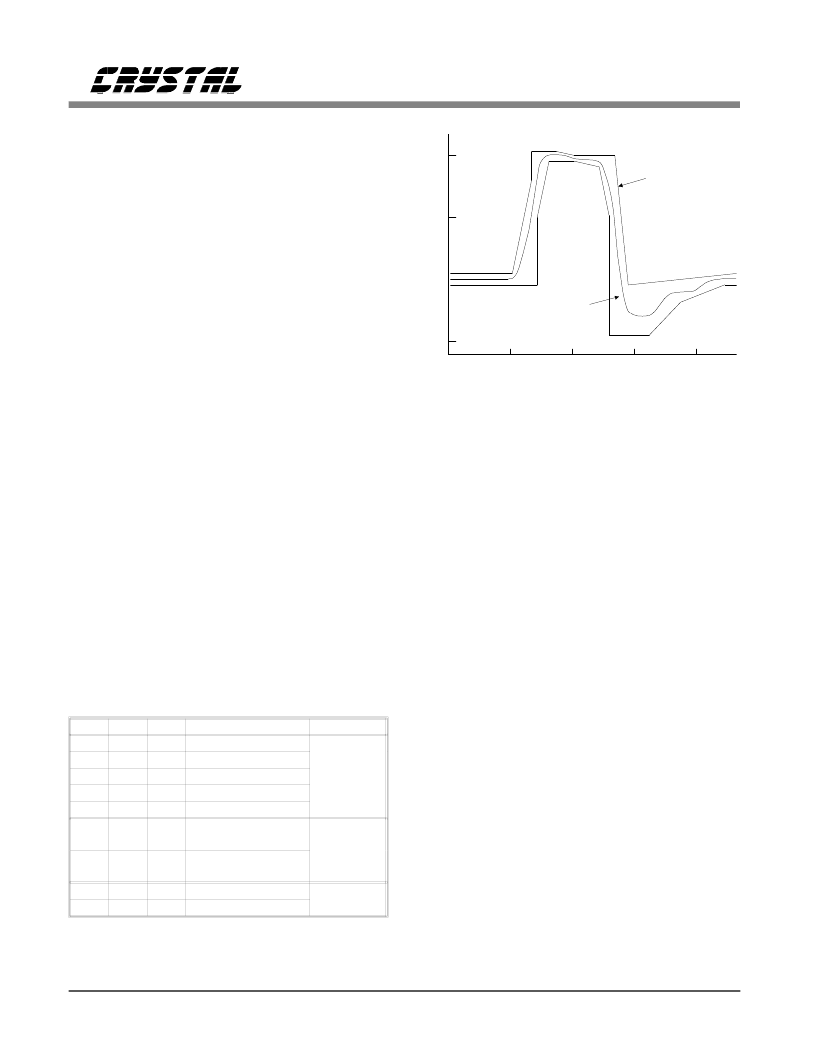
using #22 ABAM cable. A typical output pulse is
shown in Figure 8. These pulse settings can also
be used to meet CCITT pulse shape requirements
for 1.544 MHz operation.
For T1 Network Interface applications, two addi-
tional options are provided. Note that the optimal
pulse width for Part 68 (324 ns) is narrower than
the optimal pulse width for DSX-1 (350 ns). The
CS61577 automatically adjusts the pulse width
based upon the "line length" selection made.
The E1 G.703 pulse shape is supported with line
length selections LEN2/1/0=0/0/0 or
LEN2/1/0=0/0/1. As with the CS61574,
LEN2/1/0=0/0/0 supports the 120
, 3 V output
option without external series resistors, but will
also support the 75
, 2.37 V output option with
an external 4.4
resistor in series with TTIP or
TRING. The new LEN2/1/0=0/0/1 code supports
the 75
, 2.37 V output option without external
series resistors allowing for software selection be-
tween the two E1 output options. The pulse width
will meet the G.703 pulse shape template shown
in Figure 9, and specified in Table 4.
The CS61577 will detect a static TCLK, and will
force TTIP and TRING low to prevent transmis-
sion when data is not present. When any transmit
control pin (TAOS, LEN0-2 or LLOOP) is tog-
gled, the transmitter outputs will require
approximately 22 bit periods to stabilize. The
transmitter will take longer to stabilize when
RLOOP is selected because the timing circuitry
must adjust to the new frequency.
500
1.0
0.5
0
-0.5
0
250
750
1000
NORMALIZED
AMPLITUDE
AT&T CB 119
SPECIFICATIONS
PULSE SHAPE
OUTPUT
TIME (nanoseconds)
ANSI T1.102,
Figure 8. Typical Pulse Shape at DSX-1 Cross Connect
LEN2 LEN1 LEN0
0
1
1
0
1
0
1
1
1
1
0
0
Option Selected
0-133 FEET
133-266 FEET
266-399 FEET
399-533 FEET
533-655 FEET
75
(with 4.4
resistor) & 120
75
(without
4.4
resistor)
FCC PART 68, OPT. A
ANSI T1.403
Application
1
0
1
0
1
0
DSX-1
ABAM
(AT&T 600B
or 600C)
E1
CCITT G.703
0
0
1
0
0
1
1
0
1
NETWORK
INTERFACE
Table 3. Line Length Selection
CS61577
10
DS155PP2
相關(guān)PDF資料 |
PDF描述 |
|---|---|
| CS61577-IP1 | T1/E1 LINE INTERFACE |
| CS61577-IL1 | T1/E1 LINE INTERFACE |
| CS61577 | T1/E1 Line Interface(T1/E1線接口) |
| CS8 | Phase Control Thyristors |
| CS8-08IO2 | Phase Control Thyristors |
相關(guān)代理商/技術(shù)參數(shù) |
參數(shù)描述 |
|---|---|
| CS6157AT | 制造商:Rochester Electronics LLC 功能描述:- Tape and Reel |
| CS6158 | 制造商:未知廠家 制造商全稱:未知廠家 功能描述: |
| CS61581 | 制造商:CIRRUS 制造商全稱:Cirrus Logic 功能描述:T1/E1 Universal Line Interface |
| CS61581-IL | 制造商:CIRRUS 制造商全稱:Cirrus Logic 功能描述:T1/E1 Universal Line Interface |
| CS61581ILZ | 制造商:CIRRUS 功能描述:Pb Free |
發(fā)布緊急采購(gòu),3分鐘左右您將得到回復(fù)。