- 您現(xiàn)在的位置:買(mǎi)賣(mài)IC網(wǎng) > PDF目錄376558 > DAC488HR (Electronic Theatre Controls, Inc.) 16-bit D/A Converter with Digital I/O & IEEE 488 PDF資料下載
參數(shù)資料
| 型號(hào): | DAC488HR |
| 廠商: | Electronic Theatre Controls, Inc. |
| 英文描述: | 16-bit D/A Converter with Digital I/O & IEEE 488 |
| 中文描述: | 16位D / A的數(shù)字I /轉(zhuǎn)換器? |
| 文件頁(yè)數(shù): | 1/4頁(yè) |
| 文件大?。?/td> | 190K |
| 代理商: | DAC488HR |
Q U I C K F I N D
248
tel: 440-439-4091
fax: 440-439-4093
sales@iotech.com
www.iotech.com
the smart approach to instrumentation
I
Features
Two or four isolated 16-bit outputs
100-kHz/channel update rate
480 Ksamples/channel max buffer
±
1,
±
2,
±
5, &
±
10 VFS programmable
unipolar & bi-polar output ranges
One-shot, step, burst, waveform, &
continuous output modes
GET, external TTL, IEEE command,
& time event trigger sources
ASCII, binary, integer decimal, & hexa-
decimal data formats
Standard sine, square, & triangle
waveform generation
500 VDC channel-to-channel isolation
Eight digital inputs & eight digital
outputs
100 mA high-current outputs
LabVIEW
drivers
The DAC488HR
is an IEEE 488 program-
mable 16-bit D/A converter. It can be
configured with either two or four output
channels, which are optically isolated from
each other and from IEEE 488 common
by up to 500 VDC. Each channel is inde-
pendently programmable for 1, 2, 5, or 10
VFS unipolar or bipolar output, specified
as either bits or volts in ASCII, integer,
hexadecimal, or binary format. Multiple
output modes, multiple clock and trigger
sources, and buffer management enable
the DAC488HR to function as a precision
voltage source, a function generator, or
an arbitrary waveform generator.
Waveforms captured by IOtech’s 16-bit,
100-kHz ADC488A series (see p. 243) digi-
tizers can be edited and transferred to the
DAC488HR for output. The ADC488A
series and DAC488HR in combination
form a powerful waveform I/O system.
Typical applications include transducer
simulation, disk drive testing, vibration
analysis, and materials testing.
DAC488HR
16-bit D/A Converter with Digital I/O & IEEE 488
Burst Mode.
Functionally identical to step
mode, except that waveforms rather than
single values are output.
Waveform Mode.
Based on recognition
of a trigger, the waveform buffer is output
for a specified number of cycles.
Continuous Mode.
Data is continuously
input from the IEEE 488 bus and output to
an analog channel at rates up to 200 Kbytes/s
upon the detection of a specified trigger.
This mode is ideally suited for audio, speech,
and other applications that require long
duration waveforms.
Trigger Modes
The DAC488HR’s five trigger modes sup-
port a wide variety of applications.
Bus Control Mode.
Each port is programmed
to output a specified value under direct
control from the IEEE 488 bus. This mode is
useful for maintaining an initial value until
a specified condition occurs.
Step Mode.
When a specified trigger is
detected, a value is output from the
buffer, and the DAC488HR is automati-
cally re-armed until the specified buffer
count is reached. The last specified buffer
value is held as the output.
+ -
+ -
+ -
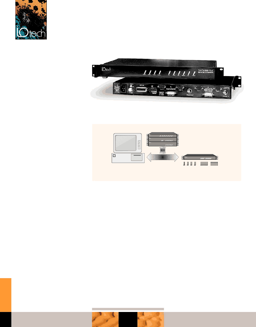
IEEE
Filter488
DAC488HR/2
SCSI488/S
DAC488HR
IEEE 488
Up to 13 IEEE 488 devices
2- isolated 100-kHz
analog outputs
outputs
inputs
DAC488HR
+ -
The versatile DAC488HR functions as a voltage source, function generator, and an arbitrary
waveform generator
相關(guān)PDF資料 |
PDF描述 |
|---|---|
| DAC4C | Converter IC |
| DAC4E | Converter IC |
| DAC5573IWR | QUAD, 8-BIT, LOW-POWER, VOLTAGE OUTPUT, INTERFACE DIGITAL-TO-ANALOG CONVERTER |
| DAC5574EVM | DAC5574 Evaluation Module(DAC5574評(píng)估模塊) |
| DAC6574EVM | DAC6574 Evaluation Module(DAC6574評(píng)估模塊) |
相關(guān)代理商/技術(shù)參數(shù) |
參數(shù)描述 |
|---|---|
| DAC488HR/2 | 制造商:未知廠家 制造商全稱(chēng):未知廠家 功能描述:16-bit D/A Converter with Digital I/O & IEEE 488 |
| DAC488HR/4 | 制造商:未知廠家 制造商全稱(chēng):未知廠家 功能描述:16-bit D/A Converter with Digital I/O & IEEE 488 |
| DAC4C | 制造商:未知廠家 制造商全稱(chēng):未知廠家 功能描述:Converter IC |
| DAC-4-CG | 制造商:Thomas & Betts 功能描述:Universal Recessed Box And Cover |
| DAC4E | 制造商:未知廠家 制造商全稱(chēng):未知廠家 功能描述:Converter IC |
發(fā)布緊急采購(gòu),3分鐘左右您將得到回復(fù)。