- 您現(xiàn)在的位置:買賣IC網(wǎng) > PDF目錄376721 > DIR1703E DIGITAL AUDIO INTERFACE RECEIVER PDF資料下載
參數(shù)資料
| 型號: | DIR1703E |
| 英文描述: | DIGITAL AUDIO INTERFACE RECEIVER |
| 中文描述: | 數(shù)字音頻接口接收機 |
| 文件頁數(shù): | 7/19頁 |
| 文件大?。?/td> | 236K |
| 代理商: | DIR1703E |

SLES007
–
JULY 2001
7
www.ti.com
system clock output
The primary function of the DIR1703 is to recover audio data and a low jitter clock from a digital audio
transmission line. The system clock (SCKO) can be selected in two clocks that are generated by the crystal
oscillator clock (crystal mode) or the PLL clock (PLL mode) by the SpAct.
The two operation modes are selected by the CKSEL pin. In the PLL clock operation mode, the clock that can
be generated is SCKO (128 / 256 / 384 / 512 f
S
, shown in Table 1), BCKO (64 f
S
), and LRCKO (1 f
S
). SCKO
is the output of the voltage controlled oscillator (VCO) in an analog PLL. The PLL function consists of a VCO,
phase and frequency detector, and a external second-order loop filter. The closed-loop transfer function, which
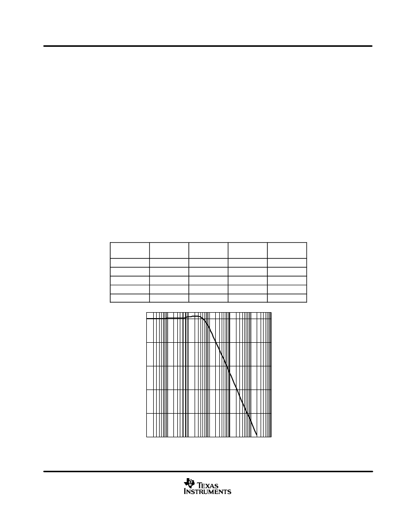
specifies the PLL jitter attenuation characteristics, is shown in Figure 2. In the crystal clock operation mode,
SCKO can be generated from several crystal oscillators shown in Table 2.
The crystal frequency should be defined for internal PLL by connecting the BRSEL pin to one of the output pins
BFRAME, EMFLG, URBIT, or CSBIT as shown in Table 3. A 12.288 MHz crystal resonator can be used for
96-kHz
–
128 f
S
(CSBIT), 48-kHz
–
256 f
S
(OPEN) and 32-kHz
–
384 f
S
(BFRAME). If BRSEL is not connected
to any pins, the 48-kHz sampling rate is selected. The system clock frequency of both modes can be selected
by control data at SCF0 and SCF1 pins shown in Table 4.
Table 5 shows the state of the system and the condition of audio clocks and flags in both the PLL and crystal
operation modes. In the crystal clock operation mode, SpAct also detects the bit rate of the incoming S/PDIF
signal and indicates the state at the UNLOCK pin. Therefore, by connecting CKSEL pin 28) to UNLOCK (pin
27), the system clock source can be selected automatically when the S/PDIF signal arrives and the bit rate is
detected. The required accuracy for clock frequency of the crystal resonator or external clock input is
±
500 ppm.
Table 1. Generated System Clock (SCKO) PLL Clock Operation Mode
SAMPLING
RATE
128 fS
256 fS
384 fS
512 fS
32 kHz
yes
yes
yes
yes
44.1 kHz
yes
yes
yes
yes
48 kHz
yes
yes
yes
yes
88.2 kHz
yes
yes
yes
yes
96 kHz
yes
yes
yes
yes
–
100
–
80
–
60
–
40
–
20
0
100
10 k
f
–
Frequency
–
kHz
1 M
100 M
C
–
1 k
100 k
10 M
Figure 2. Jitter Attenuator Characteristics With Specified Loop Filter
相關PDF資料 |
PDF描述 |
|---|---|
| DISADVANTAGE | Disadvantage of On-Chip Transient Protection (105k) |
| DISCONTINUEDPRODUCTS | Discontinued Products - August 2. 1999 |
| DISPLAY-XREF | Optoelectronic |
| DIV100 | DIV100 - DISCONTINUED PRODUCT. No longer recommended for new design. |
| DJ25E | Proximity Sensors Inductive ABS Housing |
相關代理商/技術參數(shù) |
參數(shù)描述 |
|---|---|
| DIR1703E/2K | 制造商:Texas Instruments 功能描述:Audio Interface Receiver 28-Pin SSOP T/R 制造商:Texas Instruments 功能描述:AUD INTRFC RCVR 28SSOP - Tape and Reel |
| DIR-600/E | 制造商:D-Link Networks 功能描述: |
| DIR-605L/E | 制造商:D-Link Networks 功能描述: |
| DIR-615/E | 制造商:D-Link Networks 功能描述: |
發(fā)布緊急采購,3分鐘左右您將得到回復。