參數資料
| 型號: | DLP-245PL-G |
| 廠商: | DLP Design Inc |
| 文件頁數: | 2/14頁 |
| 文件大?。?/td> | 0K |
| 描述: | MOD USB-MCU FT245RL W/18LF8722 |
| 產品目錄繪圖: | DLP-245PL-G |
| 標準包裝: | 1 |
| 系列: | USB |
| 模塊/板類型: | 開發(fā)板 |
| 適用于相關產品: | USB |
| 其它名稱: | 813-1005 |

10
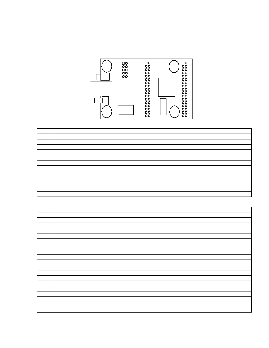
TABLE 1: DLP-245PL PINOUT DESCRIPTION
Pin #
H1 Connector Description
1
EXT5V Input 5-volt power input for board if not using USB port power.
2
GROUND
3
EXT5V Input 5-volt power input for board if not using USB port power.
4
MCLR Pull to ground to reset the microcontroller.
5
GROUND
6
GROUND
7
EXT3-5V Power input for VCCIO pin on the USB chip and microcontroller. Lower voltages require
running the microcontroller at 6MHz (PLL turned off in configuration bits).
8
GROUND
9
EXT3-5V Power input for VCCIO pin on the USB chip and microcontroller. Lower voltages require
running the microcontroller at 6MHz (PLL turned off in configuration bits).
10
GROUND
H2 Connector Description
1
F6 (I/O) Port Pin F6 connected to the 18LF8722 microcontroller. Analog input Channel 11.
2
F7 (I/O) Port Pin F7 connected to the 18LF8722 microcontroller.
3
F4 (I/O) Port Pin F4 connected to the 18LF8722 microcontroller. Analog input Channel 9.
4
F5 (I/O) Port Pin F5 connected to the 18LF8722 microcontroller. Analog input Channel 10.
5
F2 (I/O) Port Pin F2 connected to the 18LF8722 microcontroller. Analog input Channel 7.
6
F3 (I/O) Port Pin F3 connected to the 18LF8722 microcontroller. Analog input Channel 8.
7
H6 (I/O) Port Pin H6 connected to the 18LF8722 microcontroller. Analog input Channel 14.
8
H7 (I/O) Port Pin H7 connected to the 18LF8722 microcontroller. Analog input Channel 15.
9
H4 (I/O) Port Pin H4 connected to the 18LF8722 microcontroller. Analog input Channel 12.
10
H5 (I/O) Port Pin H5 connected to the 18LF8722 microcontroller. Analog input Channel 13.
11
F0 (I/O) Port Pin F0 connected to the 18LF8722 microcontroller. Analog input Channel 5.
12
F1 (I/O) Port Pin F1 connected to the 18LF8722 microcontroller. Analog input Channel 6.
13
A4 (I/O) Port Pin A4 connected to the 18LF8722 microcontroller. Open drain output.
14
A5 (I/O) Port Pin A5 connected to the 18LF8722 microcontroller. Analog input Channel 4.
15
A2 (I/O) Port Pin A2 connected to the 18LF8722 microcontroller. Analog input Channel 2.
16
A3 (I/O) Port Pin A3 connected to the 18LF8722 microcontroller. Analog input Channel 3.
17
A0 (I/O) Port Pin A0 connected to the 18LF8722 microcontroller. Analog input Channel 0.
18
A1 (I/O) Port Pin A1 connected to the 18LF8722 microcontroller. Analog input Channel 1.
19
GROUND
1
H1
H2
H3
1
相關PDF資料 |
PDF描述 |
|---|---|
| DLP-245SY-G | MODULE USB-MCU FT245RL W/SX48 |
| DLP-FPGA | MODULE USB-TO-FPGA TRAINING TOOL |
| DLP-HS-FPGA3 | MODULE USB-TO-FPGA SPARTAN 3A |
| DP83848CVVX/NOPB | TXRX ETHERNET PHYTER 48LQFP |
| DP83848HSQ/NOPB | IC TXRX ETHERNET PHYTER 40-LLP |
相關代理商/技術參數 |
參數描述 |
|---|---|
| DLP-245PL-G-CCS | 功能描述:界面開發(fā)工具 DLP-245PL PACKAGED w/CCS Compiler RoHS:否 制造商:Bourns 產品:Evaluation Boards 類型:RS-485 工具用于評估:ADM3485E 接口類型:RS-485 工作電源電壓:3.3 V |
| DLP-245SX | 功能描述:界面模塊 USB/Micro Dev Board RoHS:否 制造商:4D Systems 產品:Serial Converters 通道/端口數量: 數據速率: 接口類型:USB, UART 工作電源電壓:3.3 V, 5 V 最大工作溫度: |
| DLP-245SY | 功能描述:界面模塊 USB/Micro Dev Board RoHS:否 制造商:4D Systems 產品:Serial Converters 通道/端口數量: 數據速率: 接口類型:USB, UART 工作電源電壓:3.3 V, 5 V 最大工作溫度: |
| DLP-245SY-G | 功能描述:界面模塊 USB/Micro Dev Board RoHS:否 制造商:4D Systems 產品:Serial Converters 通道/端口數量: 數據速率: 接口類型:USB, UART 工作電源電壓:3.3 V, 5 V 最大工作溫度: |
| DLP-245SY-G-C | 功能描述:界面模塊 USB/Micro Dev Board W/GRICH C COMPILER RoHS:否 制造商:4D Systems 產品:Serial Converters 通道/端口數量: 數據速率: 接口類型:USB, UART 工作電源電壓:3.3 V, 5 V 最大工作溫度: |
發(fā)布緊急采購,3分鐘左右您將得到回復。