- 您現(xiàn)在的位置:買賣IC網(wǎng) > PDF目錄376836 > DP8440 PDF資料下載
參數(shù)資料
| 型號: | DP8440 |
| 文件頁數(shù): | 17/46頁 |
| 文件大小: | 644K |
| 代理商: | DP8440 |
第1頁第2頁第3頁第4頁第5頁第6頁第7頁第8頁第9頁第10頁第11頁第12頁第13頁第14頁第15頁第16頁當前第17頁第18頁第19頁第20頁第21頁第22頁第23頁第24頁第25頁第26頁第27頁第28頁第29頁第30頁第31頁第32頁第33頁第34頁第35頁第36頁第37頁第38頁第39頁第40頁第41頁第42頁第43頁第44頁第45頁第46頁

5.0 Accessing Modes
(Continued)
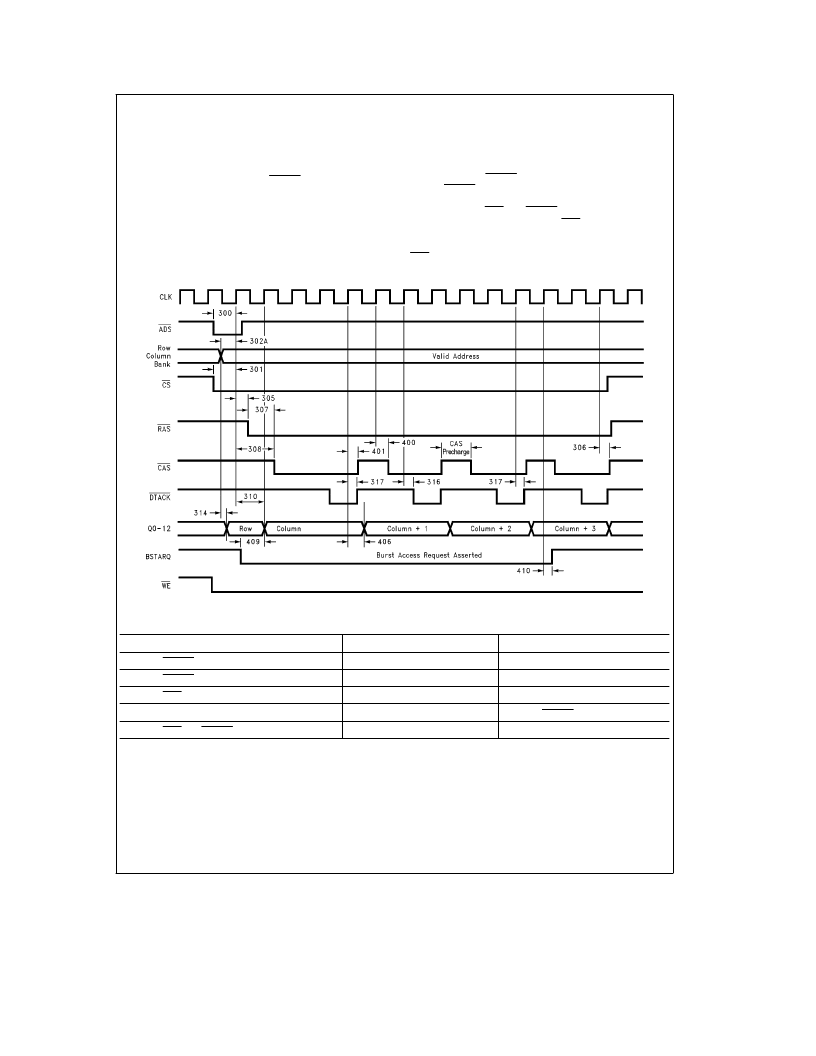
5.4 BURST ACCESS
The DP8440/41 can also perform burst accesses to several
locations in different wrap around sizes. The user requests
burst accesses by asserting the input BSTARQ. BSTARQ
must be negated before the last DTACK. This input can be
programmed to be active high or active low. The number of
burst locations can be programmable to be modulo 2, 4, 8,
or 16. If the beginning of the sequence does not start with 0,
00, 000 or 0000, the controller will wrap around. The user
may choose not to wrap by asserting the input NoWRAP, in
this case the controller will increment the column address
linearly. A NoWRAP burst access cannot cross a page
boundary unless the port is programmed in Page Mode,
in which case a Page Miss occurs and the burst access
terminates. Burst accesses can be requested at any time.
The user can do burst accesses while in Page Mode (see
Inner Page Burst), or in Normal Mode. The column address
is incremented by DTACK transitions as programmed by B0.
Thus, if DTACK is programmed as 0 T, the column address
will not be incremented and the CPU must provide the ad-
dresses to burst. CAS and DTACK can be programmed to
toggle from either clock edge. The CAS precharge time is
programmable to 1 or
(/2
clocks during read accesses and 1
or 2 clocks during write accesses (
(/2
T
e
10 ns minimum of
CAS precharge).
TL/F/11718–40
FIGURE 10. Burst Write Access
Programming Selection
Bits
Mode
DTACK during Opening
R3
e
1, R2
e
0
3T
DTACK during Burst
R5
e
1, R4
e
0
2T
CAS Precharge during Burst
C9
e
0
Read:
(/2
T, Write: 1T
Column Address Counter Control
BO
e
1
DTACK Rising Edge
CAS and DTACK Edge Select
ECAS2
e
0
Rising Edge
FIGURE 11. Burst Write Access
17
相關(guān)PDF資料 |
PDF描述 |
|---|---|
| DP8440V | DRAM Controller |
| DP8441 | |
| DP84412J | DRAM Controller |
| DP84412N | DRAM Controller |
| DP8441VLJ | DRAM Controller |
相關(guān)代理商/技術(shù)參數(shù) |
參數(shù)描述 |
|---|---|
| DP8440-40 | 制造商:NSC 制造商全稱:National Semiconductor 功能描述:microCMOS Programmable 16/64 Mbit Dynamic RAM Controller/Driver |
| DP8440V | 制造商:未知廠家 制造商全稱:未知廠家 功能描述:DRAM Controller |
| DP8440V-40 | 制造商:NSC 制造商全稱:National Semiconductor 功能描述:microCMOS Programmable 16/64 Mbit Dynamic RAM Controller/Driver |
| DP8440VLJ-25 | 制造商:Rochester Electronics LLC 功能描述:- Bulk |
| DP8440VLJ-40 | 制造商:NSC 制造商全稱:National Semiconductor 功能描述:microCMOS Programmable 16/64 Mbit Dynamic RAM Controller/Driver |
發(fā)布緊急采購,3分鐘左右您將得到回復(fù)。