- 您現(xiàn)在的位置:買賣IC網(wǎng) > PDF目錄376836 > DP84412J DRAM Controller PDF資料下載
參數(shù)資料
| 型號(hào): | DP84412J |
| 英文描述: | DRAM Controller |
| 中文描述: | DRAM控制器 |
| 文件頁(yè)數(shù): | 14/46頁(yè) |
| 文件大?。?/td> | 644K |
| 代理商: | DP84412J |
第1頁(yè)第2頁(yè)第3頁(yè)第4頁(yè)第5頁(yè)第6頁(yè)第7頁(yè)第8頁(yè)第9頁(yè)第10頁(yè)第11頁(yè)第12頁(yè)第13頁(yè)當(dāng)前第14頁(yè)第15頁(yè)第16頁(yè)第17頁(yè)第18頁(yè)第19頁(yè)第20頁(yè)第21頁(yè)第22頁(yè)第23頁(yè)第24頁(yè)第25頁(yè)第26頁(yè)第27頁(yè)第28頁(yè)第29頁(yè)第30頁(yè)第31頁(yè)第32頁(yè)第33頁(yè)第34頁(yè)第35頁(yè)第36頁(yè)第37頁(yè)第38頁(yè)第39頁(yè)第40頁(yè)第41頁(yè)第42頁(yè)第43頁(yè)第44頁(yè)第45頁(yè)第46頁(yè)

5.0 Accessing Modes
The DP8440/41 are synchronous machines. They allow the
user to access the DRAM in three different ways, Page,
Burst and Normal mode. Every one of these accesses starts
in the same way, this datasheet calls it an Opening Access.
5.1 OPENING ACCESS
Every access starts with ADS and CS asserting. ADS, CS
and the address inputs must meet setup timings with re-
spect to the next rising edge of CLK. The DP8440/41
places the row address on the Q outputs and RAS asserts
from the rising edge of CLK that ADS is set up to. The
DP8440/41 guarantees the programmed Row Address Hold
Time, t
RAH
, before switching the internal multiplexer to
place the column address on the Q outputs. After the col-
umn address is valid on the Q outputs, the controller asserts
CAS. The DRAM controller always guarantees t
ASC
of 0 ns.
DTACK asserts after RAS according to the programming
selection (R2–3). If the user programs Latch Mode, through
programming bit ECAS0, the DRAM controller latches the
column address on the rising edge of ADS (Normal or Page
Mode). If not, the controller keeps the latches in a fall
through mode.
5.2 NORMAL MODE
When the controller is programmed in Normal Mode
(B1
e
1), RAS asserts only for the programmed number of
clocks selected by R0–1, RAS Low Time, and automatically
negates from a rising clock edge. To finish the access, CAS
negates from the same clock edge at which DTACK ne-
gates. After RAS negates, the DP8440/41 will guarantee
the programmed number of positive edges of clock for RAS
precharge. RAS will not assert for another access until pre-
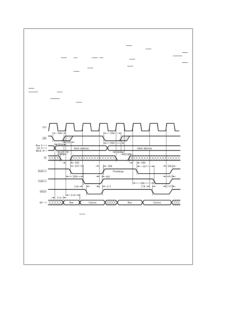
charge is met. Figure 7 shows an opening access (Normal
Mode) followed by a delayed access due to precharge (ac-
cessing the same bank). The second access is delayed by
one clock period to meet precharge time requirements.
TL/F/11718–6
FIGURE 7. A Normal Opening Access and Delayed Access
(RAS Low Time is Programmed for 2 Clocks)
14
相關(guān)PDF資料 |
PDF描述 |
|---|---|
| DP84412N | DRAM Controller |
| DP8441VLJ | DRAM Controller |
| DP84422BN | DRAM Controller |
| DP84422J | DRAM Controller |
| DP84422N | DRAM Controller |
相關(guān)代理商/技術(shù)參數(shù) |
參數(shù)描述 |
|---|---|
| DP84412J/A+ | 制造商:未知廠家 制造商全稱:未知廠家 功能描述:DRAM Controller |
| DP84412N | 制造商:未知廠家 制造商全稱:未知廠家 功能描述:DRAM Controller |
| DP84412N/A+ | 制造商:未知廠家 制造商全稱:未知廠家 功能描述:DRAM Controller |
| DP84412N/B+ | 制造商:未知廠家 制造商全稱:未知廠家 功能描述:DRAM Controller |
| DP8441VLJ | 制造商:未知廠家 制造商全稱:未知廠家 功能描述:DRAM Controller |
發(fā)布緊急采購(gòu),3分鐘左右您將得到回復(fù)。